Raspberry Pico Microcontroller
Pico Overview
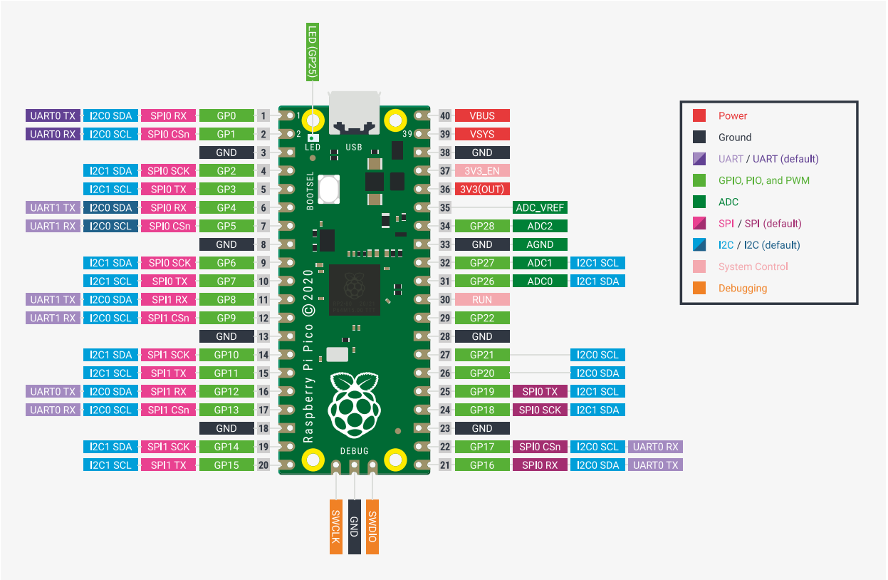
The Raspberry Pico is a development board with an RP2040 microcontroller chip. It has 264KB of SRAM and 2MB of flash memory. Development for the Pico is versatile as the platform capable of being programmed in MicroPython, CPython, C, and Rust 1. The Pico has a dual core processor with a warrantied clock speed of 133MHz, set to 125MHz out of the box 3. The Pico is easily overclocked to over double the stock processor speed, with simple overclocking available to 270MHz.There are 40 GPIO pins on the board, with SPI, I2C, and UART communication capability. The Pico comes equip with a 12-bit 500ksps ADC with 5 channels total. One channel is configured to an RP2040 internal temperature sensor, and three are tied to GPIO pins on the Pico 2. The Pico also has a timer with four alarms, a Real-Time-Counter (RTC), and sixteen Pulse-Width Modulation (PWM) channels.
ADC Configuration
Since the ADC in on the Raspberry Pico, initial setup of the ADC can easily be achieved using the ADC section of the Pico Software Development Kit (SDK) 2. This provides the engineer with a simple and straightforward introduction on taking ADC readings. However, the 12-bit ADC onboard the Pico is not great by any means. This is due to the switching power regulator on the Pico. As a result of switching signal noise, the onboard voltage reference for the ADC is setup in poor conditions. The ADC has a 30mV offset and its signal is quite noisy 1. The datasheet gives suggestions on improvement of the ADC readings. An External reference voltage may be used, the R7 resistor can be removed, or issues can be mitigated in averaging and offset code. Adding bypass capacitors to the reference voltage and ADC input pins can also improve filtering and smoothing at the cost of a larger circuit footprint. This is enough for general measurements.
 # -----------------------------------------
 #           ADC Configuration
 # -----------------------------------------
 from machine import ADC

 UPY_BIT_RES = 16
 ADC_REF = 3.3
 VOLT_PER_BIT = ADC_REF / (2**UPY_BIT_RES) # ADC receives in 2 byte packets and micropython automagically fixes it.

 adc0 = ADC(26) # Connect to GP26, which is channel 0
 adc1 = ADC(27) # Connect to GP27, which is channel 1
 # adc2 = machine.ADC(28) # Connect to GP28, which is channel 2
 adc_reading = adc0.read_u16() * VOLT_PER_BIT # read and report the ADC reading
Power Regulation and Filtering
The Pico can be powerered either through a micro USB cable or through external voltage regulation. The Pico is capable of operating on a 2.3 to 5.5V source. A simple yet effective way to safely power the Raspberry Pico externally is via the VSYS pin. This will activate the device and use the 3.3V Switching Mode Power Supply (SMPS). To avoid backflow when the Pico is plugged in via USB, this connection should be done using a Schottky diode from your source to VSYS 1. The Pico power-chain is decent because the SMPS is efficient, but noise on the output causes problems with other systems like the ADC 1, 2.
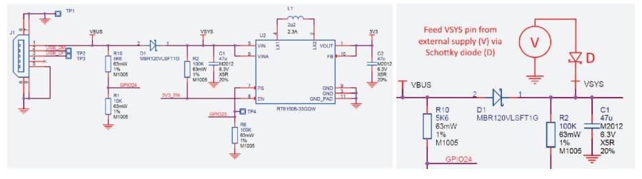
Pico Power-chain and the implemented method of external supply 1.
Changing Clock Speeds
The raspberry Pi foundation ensures operation of the Pico at 133MHz 3, however the device can work well past that frequency. Higher frequency clock speeds can lead to issues with systems and should be tested on a case by case basis. Speeds above 200MHz can interfere with UART and other USB serial communications. Speeds above 270MHz are not easily achievable without flashing to the EEPROM directly. Flashing the EEPROM can allow for clock speeds in the 400MHz range.
The Pico can also be under-clocked for better efficiency in low power and light workloads. Changing the internal clock speed with extend maximum watchdog timer periods, another perk of under-clocking.
Warning
Pushing the Raspberry Pico beyond 133MHz voids your warranty, and can shorten the lifespan of the device!
 from machine import freq

 # -----------------------------------------
 #           SYSTEM CLOCK
 # -----------------------------------------

 DEFAULT_SYS_CLK = 125_000_000
 OVERCLOCK = 270_000_000
 UNDERCLOCK = 30_000_000

 # Pico can go up to 270MHz before needing to flash to the eeprom directly.
 system_clock = OVERCLOCK

 # if the system clock is not the default, apply the clock speed.
 if system_clock !=  DEFAULT_SYS_CLK:
     freq(system_clock)

 # print(f'Clock: {freq()/1e6}MHz')
Inputs and Outputs
Buttons, switches, and LEDs are integral to most designs for various controls and system status. All inputs are easliy setup in a pull-down configuration. GPIO selected for these pins were selected last to ensure critical systems had placement. Button debouncing can be taken care of in software by implementing a delay after initial triggering. Alternatively, these buttons could be debounced using small bypass capacitors such as a 100nF, creating a RC continuous voltage response for the IO pin instead of a bouncing signal. All buttons, switches, and output LED’s should use the 3.3V source from the SMPS as to not damage GPIO pins on the Pico. LED’s should also be paired with 220-ohm resistors to give the LED’s maximum brightness in a safe current range.
 from utime import ticks_ms
 from machine import Pin

 # Button Pin Assignment
 # ----------------------------
 button0 = Pin(20, Pin.IN)
 button1 = Pin(21, Pin.IN)
 button2 = Pin(22, Pin.IN)
 button3 = Pin(28, Pin.IN)
 button_pins = [button0, button1, button2, button3]

 # -----------------------------------------
 #           GENERAL I/O
 # -----------------------------------------
 last_time = 0
 def debounce():
     global last_time
     new_time = ticks_ms()

     # if it has been more that 1/10 of a second since the last event, we have a new event
     if (new_time - last_time) > 100:
         last_time = new_time
         return True
     else:
         return False

 # These handlers are what occurs when a button is pressed.
 def button0_irq_handler(pin):
     global reset
     if (debounce()):
         reset = True

 def button1_irq_handler(pin):
     global menu_select
     if (debounce()):
         menu_select = 0

 def button2_irq_handler(pin):
     global menu_select
     if (debounce()):
         menu_select = 1

 def button3_irq_handler(pin):
     global menu_select
     if (debounce()):
         menu_select = 2

 # now we register the handler function when the button is pressed
 button0.irq(trigger=Pin.IRQ_RISING, handler = button0_irq_handler)
 button1.irq(trigger=Pin.IRQ_RISING, handler = button1_irq_handler)
 button2.irq(trigger=Pin.IRQ_RISING, handler = button2_irq_handler)
 button3.irq(trigger=Pin.IRQ_RISING, handler = button3_irq_handler)
References
- 1(1,2,3,4,5,6)
“Raspberry Pico Datasheet,” raspberrypi.com. [Online]. Available: https://datasheets.raspberrypi.com/pico/pico-datasheet.pdf. [Accessed: 15-Nov-2022].
- 2(1,2,3)
“Raspberry Pico python SDK,” raspberrypi.com. [Online]. Available: https://datasheets.raspberrypi.com/pico/raspberry-pi-pico-python-sdk.pdf. [Accessed: 15- Nov-2022].
- 3(1,2)
“RP2040 Datasheet,” raspberrypi.com. [Online]. Available: https://datasheets.raspberrypi.com/rp2040/rp2040-datasheet.pdf. [Accessed: 14-Nov-2022].