Linear Regulators
Theory
Linear regulators are basic 3-terminal devices used to maintain a constant regulated voltage 2. A regulating circuit employs a transistor operating with negative feedback to produce the desired output 5. A regulators transistor operates as a variable series resistance from the input voltage to the output voltage, with the remainder of energy being dissipated as heat [3]. Linear regulators are considered inefficient devices for this reason. However, linear regulators are excellent at creating a specific voltage with minimal noise. Their output characteristics, implementation simplicity, and adjustability make them useful devices.
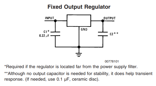
Regulators may have a fixed voltage or adjustable voltage. Some regulators even allow for both depending on the circuit configuration. Fixed regulators often have a voltage divider between the output pin and the adjust/ground pin on the device, setting the output voltage of the regulator. The same can be done externally to an adjustable regulator to set the output voltage within the device operating range. For example, the LD1085 comes as a fixed and adjustable depending on the use case.
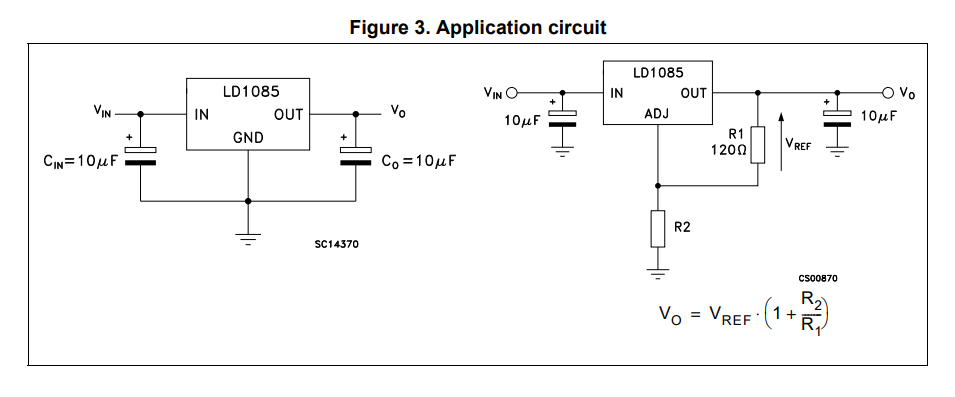
Fixed and Adjustable Regulator configuration for an LD1085 1.
A given regulator has a limited operation region. The lower boundary is determined by the reference voltage of the device. Often, this can be represented as a Zener diode in the simplified schematic. However, on chip it is more likely a bandgap reference is employed for better performance over a variety of temperatures. The reason it is called a bandgap reference comes from the fact it uses the bandgap of silicon (about 1.22 eV – electron volts) to generate a very constant voltage (~1.25V) with respect to temperature. This 1.25V reference is used for error correction of the device. The op-amp performs error correction based on the reference voltage and negative feedback from the device output.
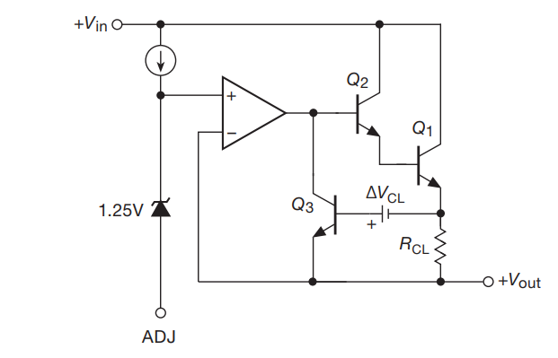
The upper limit of output is dictated by the input voltage minus the dropout voltage of the device. Dropout voltage varies between devices and leads to a category of regulators called low dropout or LDO regulators. On the LM317, voltage dropout is determined by the voltage drops over Q1, Q2, and the current limit resistor (R_CL) with Q3. If we assume each drop from base to emitter of these BJT’s is 0.7V, then there is approximately 2.1V dropout from the device. When checking the electrical characteristics of the LM317 datasheet, we can see our quick analysis is correct as the dropout is 2V 3. The Current limit resistor and Q3 operate as the devices current limiting protection. It is also worthwhile to realize that the potential difference between the output and adjust pin is equivalent to the reference voltage (~1.25V), as they are connected via the virtual short of the error amplifier. Because of these properties, linear regulators like the LM317 can be thought of as power transistors. And have a variety of uses outside of strict voltage regulation 5.
Applications
Constant Current Source
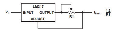
Constant current source circuit diagram of the LM317 regulator 3.
A constant current source can be made with a linear regulator when a single limit resistor is placed between the output and adjust pins. Because the potential difference between output and adjust pin is always equivalent to the reference voltage, output current is set by the series resistance.
Adjustable Voltage Source
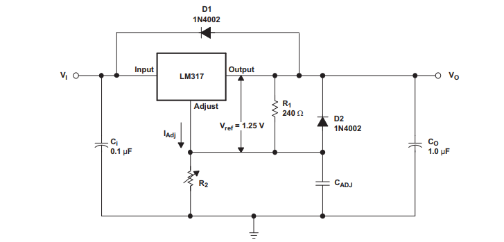
Typical application circuit diagram of the LM317 regulator 3.
A constant voltage source made using adjustable resistors allows for a variety of voltage outputs. Capacitors are employed to improve ripple rejection of the output by stabilizing various DC voltage points. Diodes can be added to provide low impedance paths for current if the input voltage is turned off. This protects against capacitors discharging into the adjust and output pins, potentially harming the device.
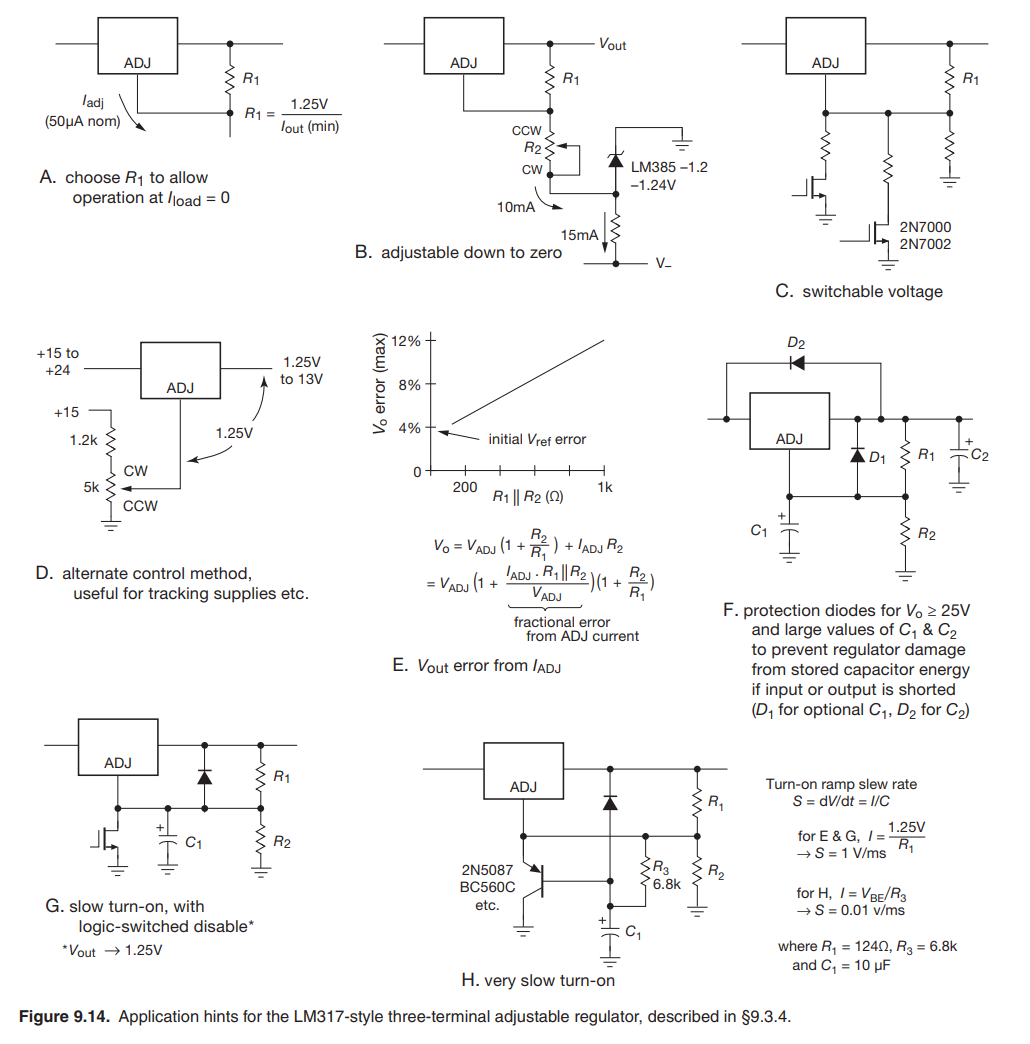
Application Hints
References
- 1
“LD1085 Datasheet: 3A low drop positive voltage regulator - adjustable and fixed,” ST Microelectronics. [Online]. Available: https://www.st.com/resource/en/datasheet/ld1085.pdf. [Accessed: 10-Mar-2023].
- 2
“Linear Regulator,” Wikipedia, 03-Mar-2023. [Online]. Available: https://en.wikipedia.org/wiki/Linear_regulator. [Accessed: 10-Mar-2023].
- 3(1,2,3)
“LM317 3-terminal adjustable regulator - Texas Instruments.” [Online]. Available: https://www.ti.com/lit/ds/symlink/lm317.pdf. [Accessed: 10-Mar-2023].
- 4
“LM78XX, LM78XXA - 3-terminal 1 a positive voltage regulator,” Fairchild Semiconductors. [Online]. Available: https://www.mouser.com/datasheet/2/149/LM7812-461970.pdf. [Accessed: 10-Mar-2023].
- 5(1,2,3,4)
P. Horowitz and W. Hill, “Chapter 9: Voltage Regulation and Power Conversion,” in The Art of Electronics, New York: Cambridge University Press, 2022.