Communication Protocols
SPI - Serial Peripheral Interface
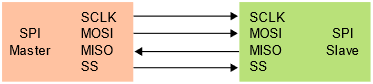
SPI is a full-duplex serial communication protocol that was created by Motorola in the 1980’s for high-speed communication in embedded systems 1. The SPI protocol consists of a single master device and one or many slave devices. For a simple two device system, A clock (SCLK), a chip select (CS), and two data lines (MOSI, MISO) are employed. MOSI is the data transmitted from the master device, while MISO is the data received from the master device.
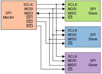
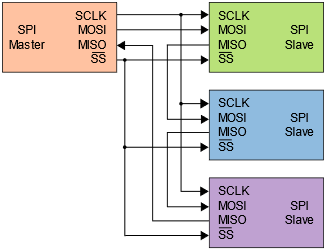
SPI can incorporate multiple slave devices by connecting data and clock lines, individually accessing a slave device by using a dedicated chip select line for each device as seen in figure 2. This can become GPIO intensive as the number of pins needed on the master device will increase with each additional slave device. Alternatively, SPI devices can work cooperatively by tying all chip selects to the same line as seen in figure 3. This works well if data does not need to be returned from the slave devices and the slave devices are intended to have the same output.
|
|
SPI independent configuration 1. |
SPI daisy-chained configuration 1. |
SPI transmits and receives data simultaneously in both directions, making the communication full duplex in design. SPI also uses GPIO for addressing a chip instead of transmitting addresses over the data lines commonly seen in I2C. Because of the full duplex data transmission and GPIO addressing, SPI has very high transmission speeds, but can become GPIO intensive. In practice, the maximum clock speeds of a SPI configuration depend highly on the connected devices and their method of connection. Finally, the SPI protocol is highly configurable in that the clock polarity and phase can be configured. This is also highly dependent on connected devices and should be considered when creating a two-device or multi-device system. In terms of using SPI on a microprocessor, A clock at or below 1MHz is best for breadboarding and flywire use.
I2C - Inter-Integrated Circuit
I2C is a half-duplex serial communication protocol created by Phillips Semiconductor in the 1980’s for low-speed communication in embedded systems. [2] The I2C protocol consists of a serial data line (SDA) and a serial clock line (SCL). These serial wires receive weak pull-up resistors to default the communication wire to the logical high voltage. Raw communication speed is limited by the device interacting, however 100kbps or 400kpbs is common. I2C is half-duplex as data is bidirectional but can only communicate in one direction at a given time.
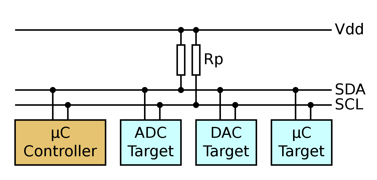
Interaction between I2C devices utilizes addresses, allowing for multiple master and multiple slave devices. This allows for circuit design simplicity as only two wires are required regardless of the number of devices. However, addressing of devices will fail if more than one device uses a specific address. I2C is also limited in communication speed because of the two-wire interface but is further restricted by device addressing overhead for each transaction.
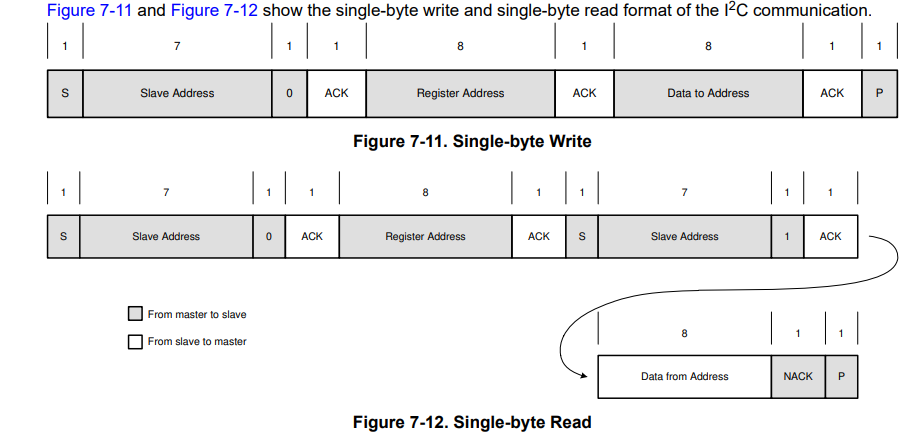
Communication between I2C devices occurs when a master device produces a start signal to initiate communication. The master device will start providing a clock signal while a slave device is addressed over the data line with its unique 7-bit address. This is the address data frame. After every data frame, the master queries for acknowledgement from the slave device. The master device then commands a read or write to the slave device using a register data frame. In the case of writing data, a write data frame will then be sent to the slave device. In the case of reading data, another address data frame is sent before the slave device returns the data. Multi-read and multi-write transactions can occur where extra data frames are added to the end of transactions for communication of larger consecutive amounts of information.
References
- 1(1,2,3,4)
“Serial peripheral interface,” Wikipedia, 27-Sep-2022. [Online]. Available: https://en.wikipedia.org/wiki/Serial_Peripheral_Interface. [Accessed: 19-Oct-2022].
- 2(1,2)
“I2C Communication Protocol.” Wikipedia, Wikimedia Foundation, Oct. 3, 2023. [Online]. Available: [en.wikipedia.org/wiki/I%C2%B2C]. Accessed: Dec. 2, 2023.