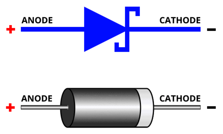
Diodes

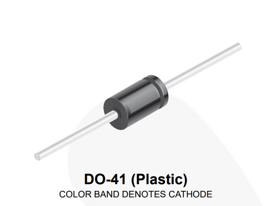
General Purpose Diode.
Theory
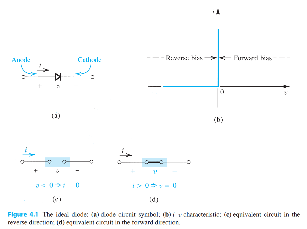
Ideal Diode I/V characteristics [1].
Diodes are nonlinear devices that operate as electrical ‘check valves’ by allowing current flow in one direction and blocking current flow in the other direction. An ideal diode would behave as a short circuit when forward biased, and an open current when reverse biased. While real diodes cannot match the ideal diode exactly, diodes perform close enough to ideal for many applications with some caveats. Forward bias, Reverse bias, and the Breakdown region showcase their own non-idealities, which can be seen in the figure below.
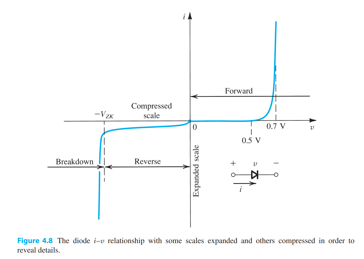
Realistic Diode I/V characteristics with scale changed for detail expression [1].
In the Forward Bias region, Diodes exponentially increase the current conducted based on applied voltage. A forward voltage applied to a diode is required to conduct current, and is often assumed to be ~0.7V. Current through the diode is based on a diodes physical parameters and temperature, giving constant of Is and Vt respectively. Vt is approximately 25mV at 25 °C
Note
For most purposes, applying the forward voltage of a diode will conduct enough current to be considered “ON”, knowing the exact current allowed through a diode is not often needed and the current equation is truly just an approximation. What is important is to understand that there is a region between zero and the forward voltage threshold that allows a trickle of current before full conduction. It should also be known that if the circuit could be current limited if the applied forward voltage is not high enough.
In the Reverse Bias region, current can ‘leak’ backwards based on the saturation current Is. While this value is small, should still be considered for precision circuits. Current leakage becomes worse with respect to the negative voltage applied and rising temperature. Leakage continues until the diode breakdown voltage Vzk is reached, leading to a spike in reverse current. Vzk refers to the voltage of the Zener Knee, a useful parameter when working with zener diodes.
Diode Types
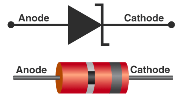
Rectifier Diodes
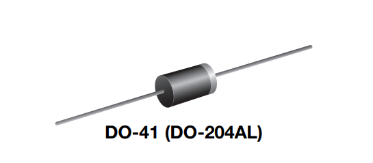
A Common Rectifier Diode.
Rectifier Diodes are general purpose diodes used for common rectification tasks. They often support higher voltages (< 1000V) and currents (< 5A) at the expense of more leakage current and junction capacitance. Rectifier diodes often need a forward voltage of 0.7 to 1.5V. This is generally acceptable since the use case is often 120V-AC adapters for household power.
Common Rectifier Diodes include:
1N400X Series (1A)
1N539X Series (1.5A)
1N540X Series (3A)
RL20X Series (2A)
Switching Diodes
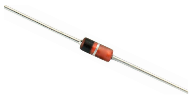
A Common Switching Diode.
Switching diodes were originally designed for small-signal circuits requiring fast switching speeds. They support a variety of voltage levels (< 100V) with low current (< 300mA). Switching diodes are more often employed in logic-level circuits, and a fast recovery time compared to general rectifiers. Switching diodes also have more typical forward voltages, with values ranging from 0.6 to 1V
Common Switching Diodes include:
1N914
1N4148 (newer 1N914)
Fast Recovery Diodes
A Common Fast Recovery Diode.
Fast recovery diodes combine elements of general purpose rectifier diodes and switching diodes. Fast recovery diodes often tolerate high voltage (< 1000V) and current (< 3A) much like a rectifier diode, but can operate at high speeds similar to a switching diode. This suits Fast Recovery Diodes to Switching power applications that Schottky diodes cannot withstand.
Common Fast Recovery Diodes include:
FR10X (1A)
FR20X (2A)
UF400X (1A)
Schottky Diodes
A Common Schottky Diode.
Schottky diodes are designed for small forward voltages (~0.1-0.5V) at the expense of lower breakdown thresholds and increased leakage. Maximum voltage tolerances range from 20 to 40V with comparable current to a general rectifier (~1-3A). Schottky diodes also have fast response for high frequency applications. This makes schottky diodes suited well for general use cases with low power and for switching applications like a DC-DC converter. Schottky diodes can even outperform switching diodes and fast recovery diodes in switching recovery time.
Common Schottky Diodes include:
1N581X (1A)
1N582X (2-3A)
Zener Diodes
A Common Zener Diode.
Zener Diodes are diodes designed to operate in the reverse breakdown region. For this reason, they are used in voltage regulation, reference, and clamping circuits. Zener diodes often have a maximum power rating coupled with a Zener voltage and a maximum regulator current.
Note
Zener Diodes have relatively stable performance in the 5V+ range. A Zener diode made for a lesser voltage will have significant variance in it’s output. 2
Common Zener Diodes include:
1N47XX (1W)
1N75XA (0.5W)
1N7522XB (0.5W)
Light Emitting Diodes
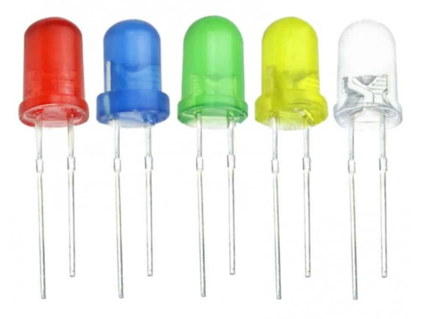
A Common LED.
LED’s are diodes that emit light when current flows through it. The color of emitted light corresponds to the semiconductors bandgap. Different semiconductors produce various colors and require different forward voltages to operate. Light intensity directly corresponds to the current flowing through it.
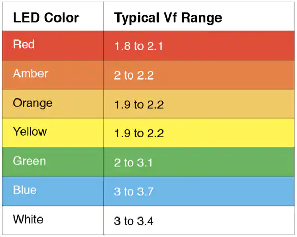
LED Forward Voltage by Color.
Photodiodes
Photodiodes are diodes that conduct when light is absorbed.
Applications
Half-Wave Rectifier
Full-Bridge Rectifier
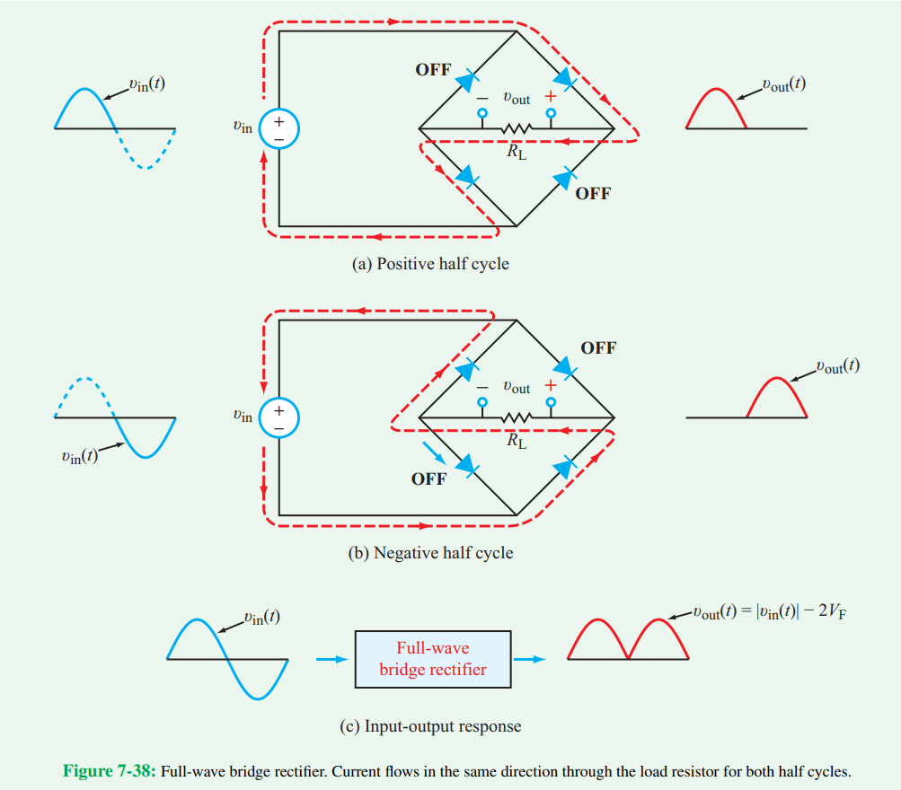
A full wave bridge rectifier.
A full bridge rectifier is a commonly configured circuit with four diodes in a diamond pattern, such that current is consistently flowing across the two terminals in the same direction during both the negative and positive cycle of the AC waveform. This creates a rectified waveform, essentially taking the magnitude of the input waveform. Although sometimes negligible, there is a small voltage loss that occurs through a full bridge rectifier, equivalent to two forward voltage drops (~1.4V). This means output peak voltage is equivalent to the input peak voltage minus the voltage drop seen at the rectifier. Losses can be minimized by using a rectifier IC or specific diodes that meet the specifications of the project.
Three Phase Rectifier
Voltage Doubling
See also
Voltage Limiting
Voltage Clamping
Inductor Flyback
Zener Regulation
References
- 1
A. S. Sedra, K. C. Smith, T. C. Carusone, and V. Gaudet, “Chapter 4: Diodes” in Microelectronic circuits, New York, NY: Oxford University Press, 2021, pp. 175–230.
- 2
P. Horowitz and W. Hill, “Chapter 1: Foundations” in The Art of Electronics, New York: Cambridge University Press, 2022.