Circuit Foundations
Ohms Law
In any given circuit, there are values that we want to observe change over time. All of circuits revolves around the relationships between these three values.
Voltage (V) - The difference in electric potential between two points. It is derived from a joule of work needed to move a coulomb of charge through a potential difference of 1 volt. 1 Voltage is measured across components. Voltages can be generated from energy sources, and applying voltages across devices create a current.
Current (I) - The rate of electron flow through a point. 1 Amp is a speed derived from flow of 1 coulomb of charge per second. From a practical perspective, current is thought to flow from the higher potential to the lower potential. However, electron flow occurs from the more negative (lower) potential to the positive (higher) potential. Current is measured through components.
Resistance (Ω) - Resistance is the opposition to flow of electric current. Resistivity is inverse to conductivity. Resistance is measured in Ohms and defined with the omega (Ω) symbol. Ohm’s Law says that 1Ω of resistance is equivalent to 1 volt supplying 1 Amp of current.
The relationship between these three values creates Ohm’s Law.
KCL: Kirchhoff’s current law
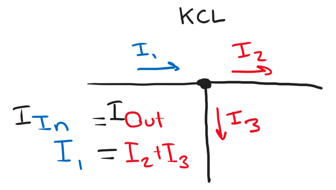
KCL in a circuit node.
The sum of currents into a point is equal to the sum of currents out of the point. KCL can be used for Nodal Analysis, observing the current in and out of a node to find voltage drops or resistor values.
KVL: Kirchhoff’s voltage law
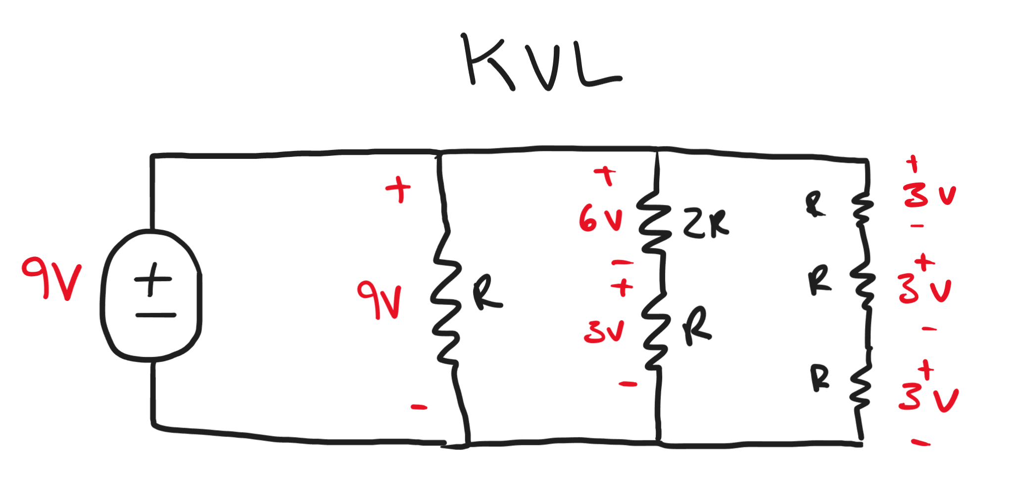
KVL seen in a circuit.
The sum of voltage differences around a closed circuit is zero. Any parallel circuit will see the same potential difference between two points. In the above figure, the two points are seen as the top and bottom rails. KVL can be used to perform Mesh Analysis by observing closed circuits in parallel and finding the current based on equivalent voltage drops.
Power
The power supplied or consumed by a circuit is equivalent to the Voltage applied times the Current created. This is (Energy / charge) * (charge / time). Power is measured in Watts (W) and is equivalent to 1 Joule per second.
Series and Parallel
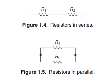
Resistors when placed in series effectively combine their resistance. Series
Whereas Parallel or Shunt resistors will effectively create a smaller resistor.
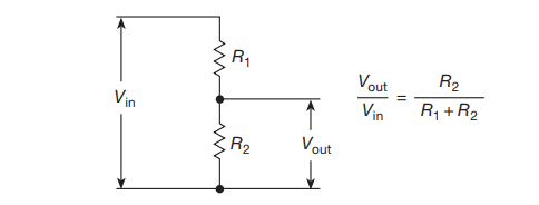
Voltage Dividers
Voltage dividers are a commonly used circuit takes a voltage input and create a voltage output that is a fraction of original size. Voltage dividers do this predictably and consistently.
Thevenin and Norton Equivalent
Thevenin’s theorem states that any two terminal network of resistors and voltage sources can be represented as an equivalent single resistor and voltage source in series. This can be found by finding the open circuit voltage across the two nodes, and the short circuit current that would occur if you shorted the two nodes. From these values, Kirchhoff’s laws, and ohm’s law, you can deduce the Thevenin equivalent circuit.
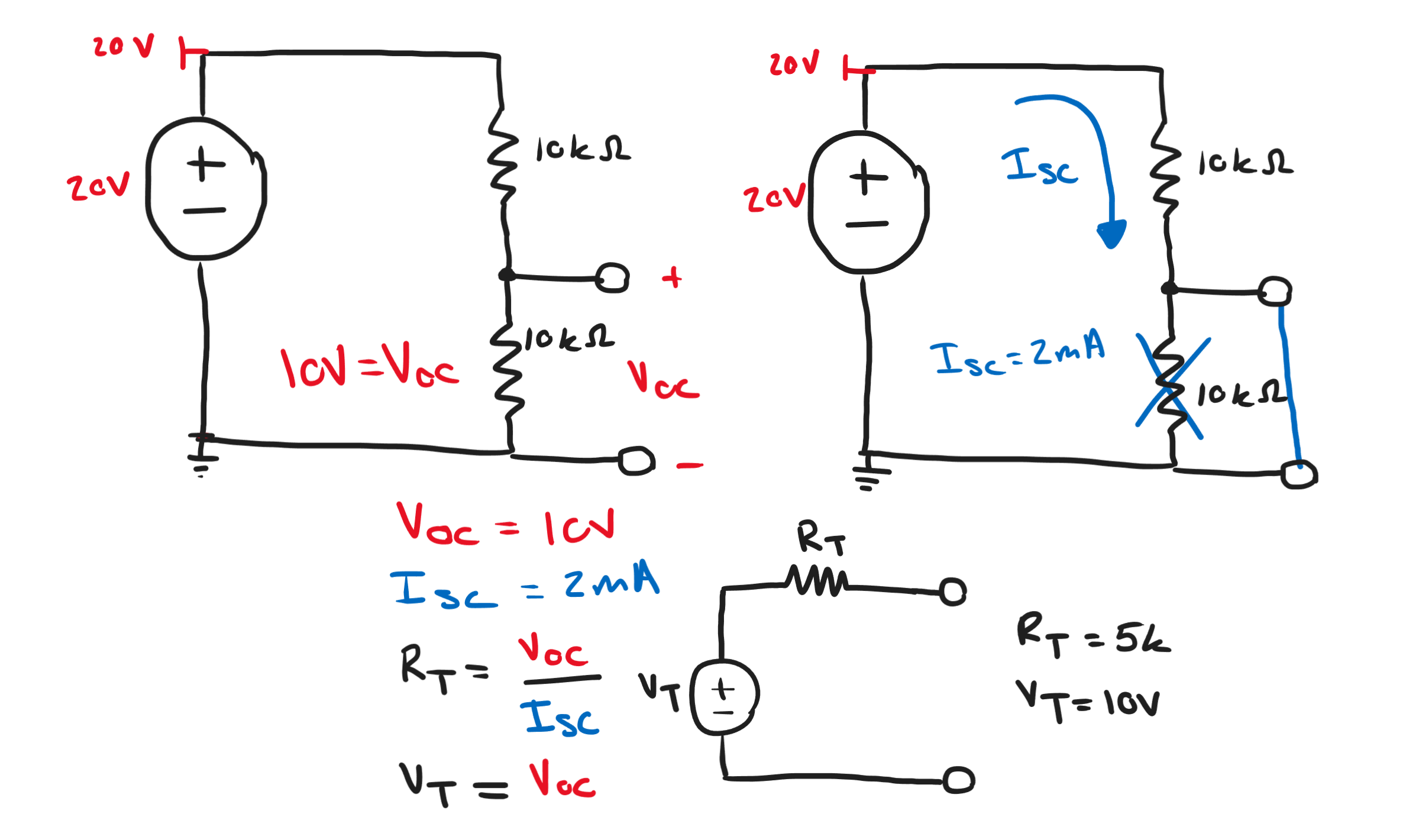
A Thevenin equivalent circuit for a voltage divider circuit.
Norton’s theorem states that any two terminal network of resistors and voltage sources can be represented as an equivalent single resistor and current source in parallel. This can be found by finding the open circuit voltage across the two nodes, and the short circuit current that would occur if you shorted the two nodes. From these values, Kirchhoff’s laws, and ohm’s law, you can deduce the Norton equivalent circuit.
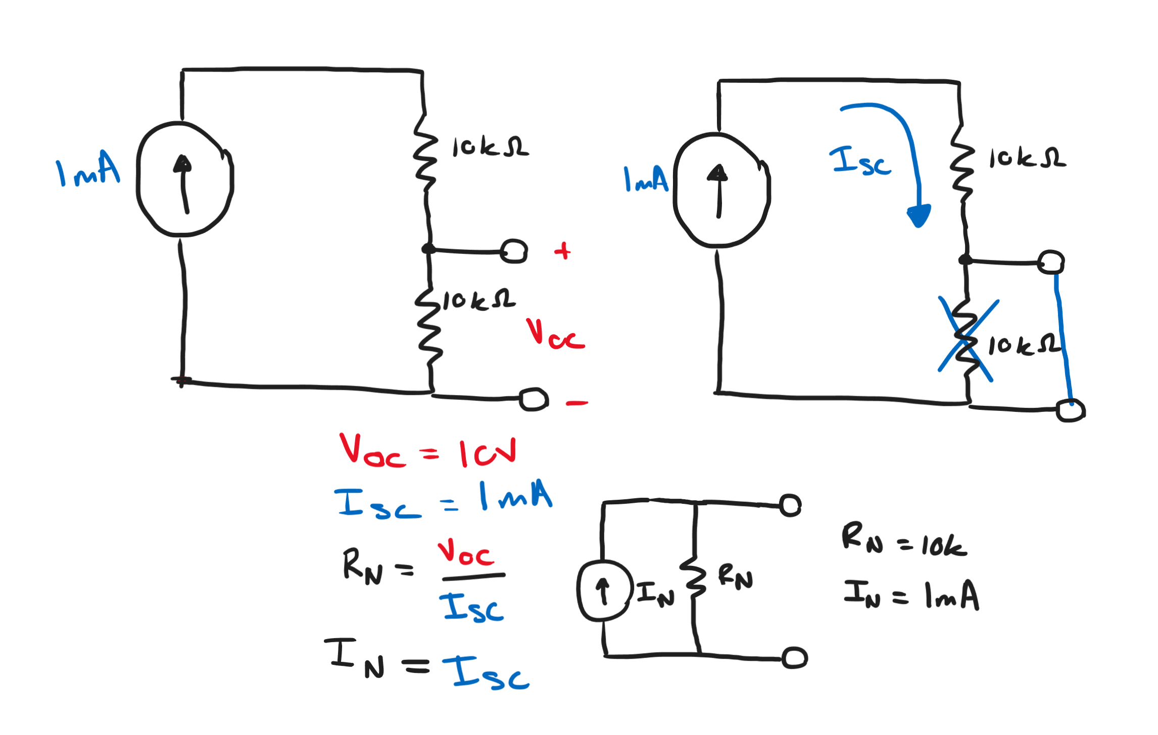
A Norton equivalent circuit for a voltage divider circuit.
Decibel Representation
Relative amplitude of signals are often measured on a logarithmic scale of Decibels (dB). Power in decibel notation can be found using the following. Decibel notation is convenient because a difference in 10dB expresses a magnitude of change in power. Thus, a 30dBW difference is equivalent to 1000W difference.
When representing voltage in decibel notation, the following equations are used.
References