Active Filters
First-Order Filter Theory
Analog filters are a method of reducing gain of responses at certain frequencies. First-order filters implement a singular cutoff frequency while second order filters implement multiple cutoff frequencies. Filters can be implemented in active and passive configurations, meaning with and without Op-Amps respectively. Regardless of a filter being passive or active, Filter frequencies and modes of operation are created between RL and RC components. Figure 1 implements passive and active filters in multiple filter configurations.
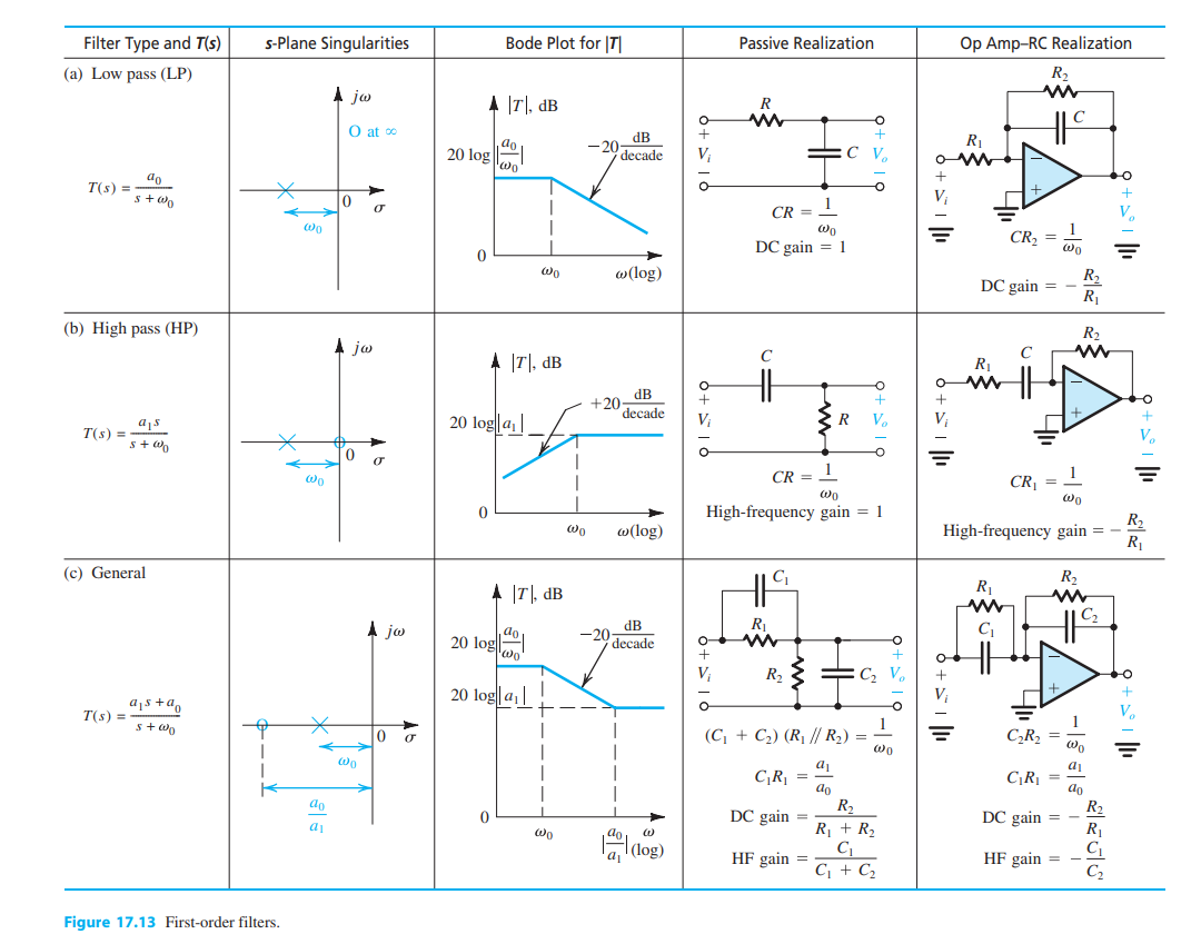
First order filter table with active and passive applications 1.
Filter Responses: Butterworth, Bessel, and Chebyshev
Responses of real filters have three idealities in the form of Butterworth, Bessel, and Chebyshev filters. Each focus on different characteristics with various tradeoffs, approximating an ideal response. The filter with the flattest possible passband response is the Butterworth filter 2. Pulse and step responses with a Butterworth filter have minor overshoot and ringing. Attenuation of the Butterworth filter is -20dB per pole. The Butterworth filter is an overall well performing filter. The main drawback of a Butterworth filter is the large transition region between the passband and the stopband.
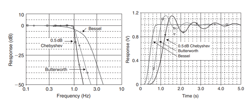
Magnitude Response and Step Response of Butterworth, Bessel, and Chebyshev filters 3.
Response of the Chebyshev filter has a steeper attenuation compared to the Butterworth, with the disadvantage of overshoot and ringing in the passband 2. Chebyshev filters have their cutoff at the point where the response falls below the ripple band. These filters are best for sharp frequency filter cutoffs. In contrast, the Bessel filter has maximally flat time delay, with very little overshoot and ringing. Bessel filters can preserve the wave shape of the original filter signal. The drawbacks of Bessel filters are associated with its shallow attenuation and large transition region. Bessel filters are also not as flat in its magnitude response as Butterworth filters.
Filter Realization: Sallen-Key Configuration
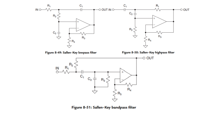
The Sallen-Key is a popular topology for active filters configuration as it has the least dependence on the Op-Amp performance. This is due to the Op-Amp being configured as an amplifier instead of an integrator 3. The configuration also allows for ratio values for passive components are low, which is good for large-scale manufacturing. However, the Sallen-Key is not easily tuned, which can be a serious drawback in choosing this topology. The quality factor of the circuit will also impact gain of bandpass configurations. Sallen-Key is a great topology if gain accuracy is important, a unity-gain filter is used, and the quality factor Q is low 2.
Filter Realization: Multiple Feedback Configuration
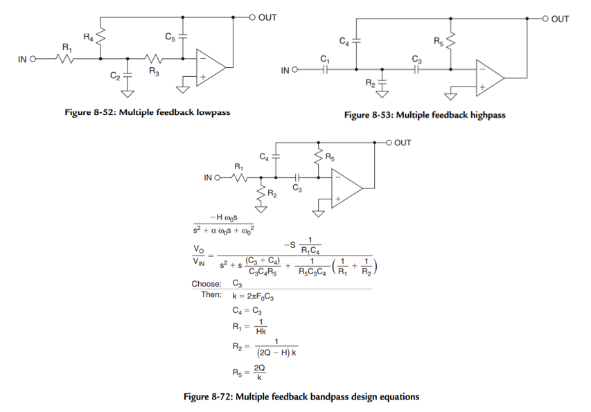
Another topology for composing filters is the multiple feedback configuration (MFB). This uses the Op-Amp as an integrator, so it is more dependent on Op-Amp characteristics than the Sallen-Key configuration 3. Ratios between maximum and minimum passive component values are larger than the Sallen-Key as well. MFB is preferable due to its low sensitivity to variation in components. It is relatively easy to tune filter characteristics 2. It should also be known that the MFB configuration inverts the signal, so pairs of two should be employed to avoid output signal inversion.
References
- 1
A. S. Sedra, K. C. Smith, T. C. Carusone, and V. Gaudet, “Chapter 2: Operational Amplifiers,” in Microelectronic circuits, New York, NY: Oxford University Press, 2021, pp. 60–73.
- 2(1,2,3,4)
“FilterPro™ user’s Guide - Ti.com,” Texas Instruments, Feb-2011. [Online]. Available: https://www.ti.com/lit/an/sbfa001b/sbfa001b.pdf. [Accessed: 14-Nov-2022].
- 3(1,2,3,4,5)
H. Zumbahlen, “Chapter 8: Analog Filters,” in Linear Circuit Design Handbook, Oxford: Newnes, 2008.