Operational Amplifiers
Ideal Op-Amp
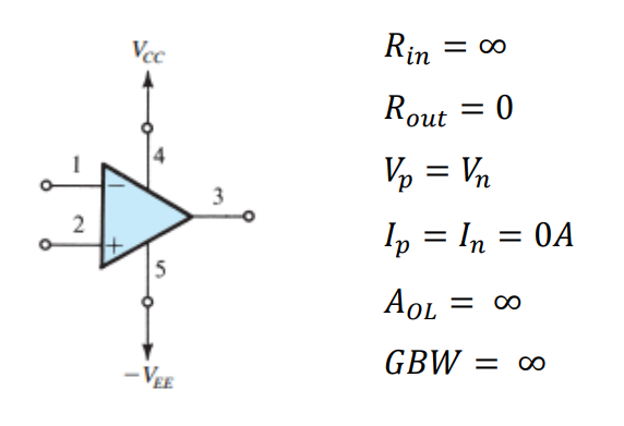
Operational Amplifiers (Op-Amps) are high-gain voltage amplifiers with differential input and a single voltage output. Op-Amps typically have five terminals: An inverting input, non-inverting input, an upper supply, a lower supply, and an output. An ideal Op-Amp has an infinite input resistance and zero output resistance. As a result, input terminals see zero current. Input terminals also see equivalent voltages. Lastly, ideal op-amps experience infinite open-loop gain and infinite Gain Bandwidth (GBW).
Using an infinite open-loop gain is limiting, as the output voltage signal would become saturated immediately. This could be useful in a comparator circuit. However, for most purposes some form of negative feedback is implemented to create a closed loop gain within the boundaries of the supply rails. Negative feedback amplifiers come in inverting (Figure 2) and non-inverting (Figure 3) configurations, with gain determined by the ratio of resistances seen by the negative feedback loop.
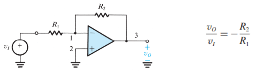
Inverting Op-Amp configuration and voltage gain equation 1.
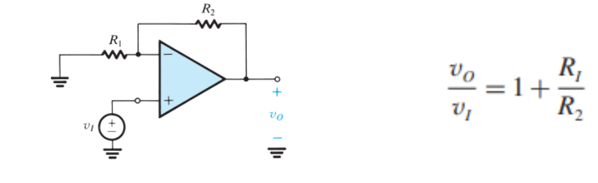
Non-inverting Op-Amp configuration and voltage gain equation 1.
Op Amp Non-Idealities
Non-idealities of real-life Op-Amps will also affect the circuit, the most influential of which is determined by a given IC’s strengths and weaknesses. A notable non-ideality can be seen in gain bandwidth and subsequent frequency response. Finite GBW/GBP of an Op-Amp produces attributes of an active lowpass filter. With the lower cutoff frequency determined by the GBP divided by the gain of the circuit 2. As a result, open-loop response often has high gain with very low cutoff frequency. Whereas closed-loop gain will keep gain approximately constant for a much wider bandwidth.
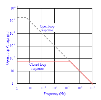
LM741 Frequency response in open and closed loop configurations 3.
Other non-idealities of Op-Amps are limits on output current, voltage, and slew rate. Output voltage can become saturated due to voltage gain exceeding the supply rails. Current supplied by an Op-Amp IC is highly dependent on a model, and current limits may be imposed for safety of the internal circuitry. The maximum rate of change for an Op-Amps output voltage is referred to as its slew rate. Op-Amps are slew rate limited at frequencies of operation that require a faster rate than the IC can permit.
Applications
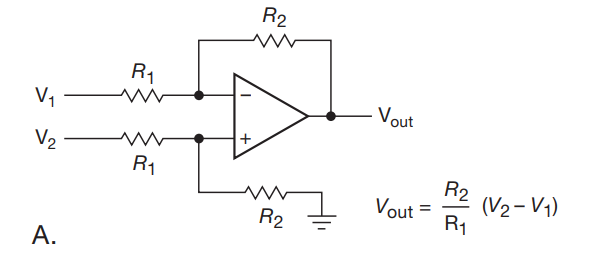
Figure 9: Simple difference amplifier with matched resistors 4
Difference Amplifiers are simple way to find the difference between two voltages, also known as a voltage subtractor. An output voltage is created that is proportional to the difference between two voltages. If all resistors are the same value, then the circuit is considered a unity gain differential amplifier and the output voltage is equal to the difference between the input voltages. An important note of this circuit is that the output can be positive or negative with respect to the reference or ground. Depending on the circuit, a dual supply may be needed, or the reference point may need to be offset. Either of these approaches could be used to capture negative values of the voltage difference observed.
References
- 1(1,2,3)
A. S. Sedra, K. C. Smith, T. C. Carusone, and V. Gaudet, “Chapter 2: Operational Amplifiers,” in Microelectronic circuits, New York, NY: Oxford University Press, 2021, pp. 60–73.
- 2
H. Zumbahlen, “Chapter 8: Analog Filters,” in Linear Circuit Design Handbook, Oxford: Newnes, 2008.
- 3(1,2)
I. Poole, “OP AMP frequency response & gain bandwidth product,” Electronics Notes, 30- Nov-2021. [Online]. Available: https://www.electronicsnotes.com/articles/analogue_circuits/operational-amplifier-op-amp/gain-bandwidthproduct-frequency-response.php. [Accessed: 31-Oct-2022].
- 4
Horowitz and W. Hill, “The Art of Electronics.” Cambridge University Press, 2022.