Raspberry Pico Development board
Date: 12/2022
Revision: 1
Raspberry Pico Development Board
Introduction
The Raspberry Pico is a powerful and inexpensive microcontroller that can be used for a variety of projects. However, the Raspberry Pi Foundation prioritized factors of size, efficiency, and cost when creating the board. This leaves certain drawbacks of the microcontroller that are well documented in the Pico datasheet 15. In this project, I aim to solve a few minor inconveniences of the Pico’s design and create a development board better suited to approaching projects. Fixes include a reset button, an off switch for the onboard SMPS, LDO voltage regulators, and better ADC performance. Additionally, Parallel 16x2 LCD display, two 10-bit DAC channels, and SD card R/W capability are added to allow the development board to act as a drop in test bench for relaying or saving information.
Methods
See also
This device focuses on ADCs, DACs, and displays to streamline development of a project. Concepts and components from the pages below are employed. Topics that required greater detail for clarification are revisited.
ADC Configuration
Since the ADC in on the Raspberry Pico, initial setup of the ADC can easily be achieved using the ADC section of the Pico Software Development Kit (SDK) 14. This provides the engineer with a simple and straightforward introduction on taking ADC readings. However, the 12-bit ADC onboard the Pico is not great by any means. This is due to the switching power regulator on the Pico. As a result of switching signal noise, the onboard voltage reference for the ADC is setup in poor conditions. The ADC has a 30mV offset and its signal is quite noisy 13. The datasheet gives suggestions on improvement of the ADC readings. An External reference voltage may be used, the R7 resistor can be removed, or issues can be mitigated in averaging and offset code. I chose a different route entirely, by adding bypass capacitors to the reference voltage and ADC input pins for filtering and smoothing.
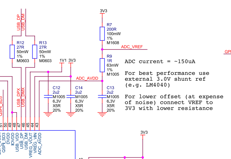
The Approach taken in this circuit was to provide an external power source and bypass the SMPS entirely. By incorporating a series of LDO’s we are able to create 5V and 3.3V rails with minimal noise. Driving the Pico via a 3.3V LDO feeds the ADC reference through a lowpass filter onboard. This creates a significant improvement from ADC SMPS measurements. However, since the entire Pico is supplied through the LDO 3.3V rail, voltage spikes and drops may occur from computations occurring on the device. This could be further mitigated by exclusively feeding the Pico’s ADC reference with a 3.3V LDO and removing the R7 resistor on the device. This would disconnect the internal 3.3V rail from the ADC reference entirely.
Power Regulation and Filtering
To supply power to the system, I chose to use the LDL1117 5V and 3.3V low-dropout regulators. This allows for a 9-12V DC source to supply the devices without much overhead. This provided a smooth 5V and 3.3V source for most components, with local decoupling capacitors where needed.
In addition to the 5V source, I powered the Raspberry Pico via the VSYS node to activate the device and use the 3.3V Switching Mode Power Supply (SMPS). This was done using a Schottky diode from 5V to VSYS to avoid backflow when the Pico is plugged in via USB 13. The Pico power-chain is good because the SMPS is efficient, but noise on the output causes problems with other systems like the ADC 13, 14. As a result, I byapassed the SMPS entirely by incorporating a shutoff switch for the SMPS.
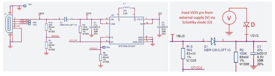
Figure 18: Pico Power-chain and the implemented method of external supply [8]_.
SD Card Reader
An SD card reader has been added via SPI 16. This permits the user to incorporate data collection over time via sensors and ADC readings. These data readings can be written to text or csv files on a SD card for post test analysis.
Inputs and Outputs
A physical reset button was added to the development board to interrupt the RUN pin on the Pico. When this pin is connected to ground, the device will shut off. To insure proper reset, hold the reset button for 3 seconds. This will guarantee that the Pico has been discharged. The Pico has a full array of female headers for easy pinout access and another for seating the pico onboard. Pinout names have been added to the silkscreen simplify development.
Schematic and PCB Design
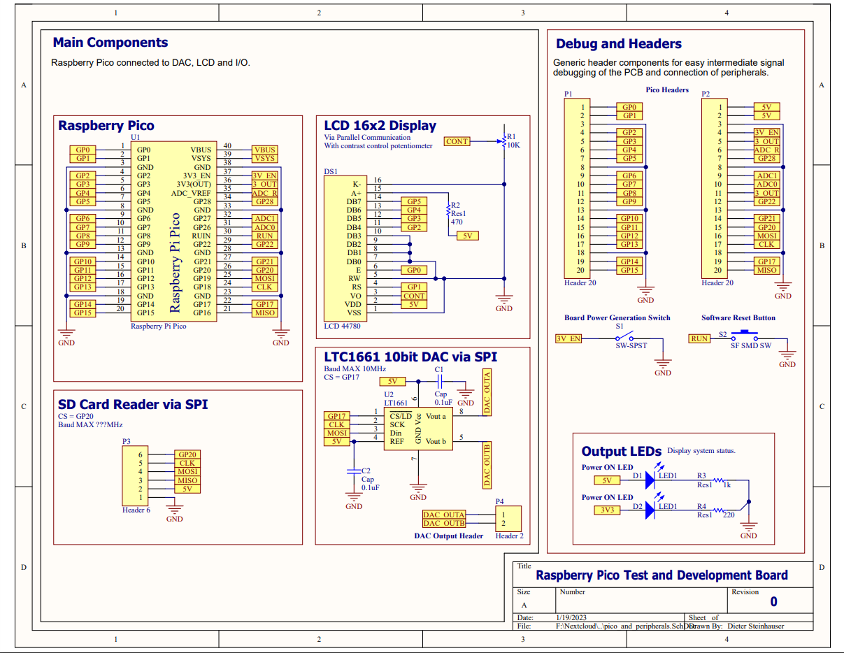
Figure 22: Devboard schematic page 1 of 2.
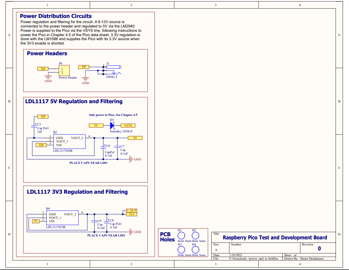
Figure 23: Devboard schematic page 2 of 2.
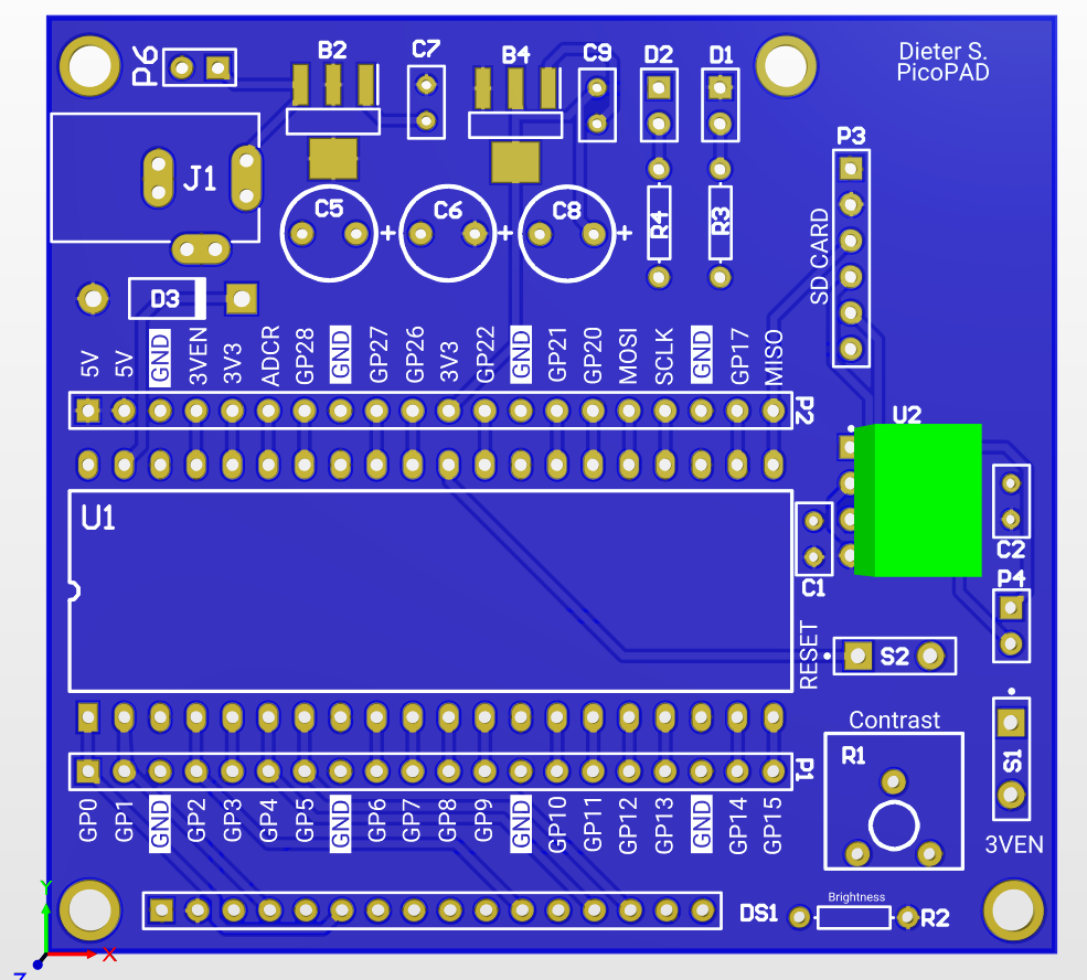
Figure 24: Top side of Devboard PCB layout.
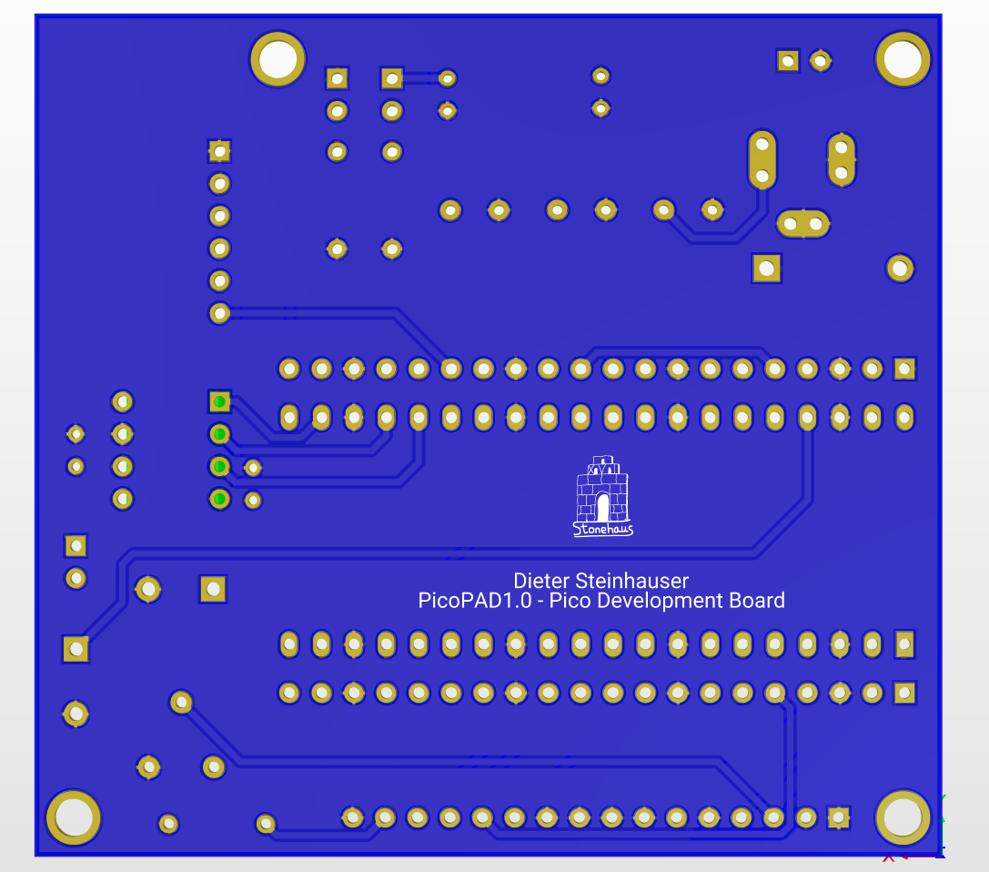
Figure 24: Bottom side of Devboard PCB layout.
Bill Of Materials
Results
The schematic of the circuit and PCB turned out well, with minimal errors. The assembled PCB was easy to debug because of its plentiful headers employed in the diagram. Also, using female headers for the ultrasonic sensors, LCD, DIP packages, and potentiometers aided debug and ensured that any errors in design could be more easily fixed if the PCB was routed wrong. Thankfully, there were no design breaking errors in this circuit, and most components worked immediately after installation.
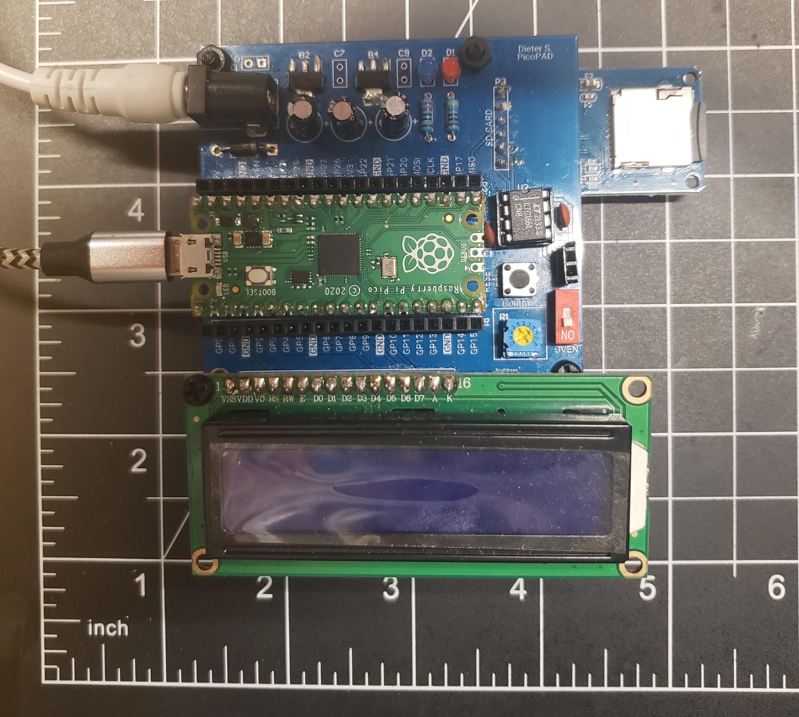
Figure 42: Raspberry Pico Development Board
Power
The power regulation and filtering produced a 5V and 3.3V source with minimal noise, observed with as little as 10mV ripple on both sources.
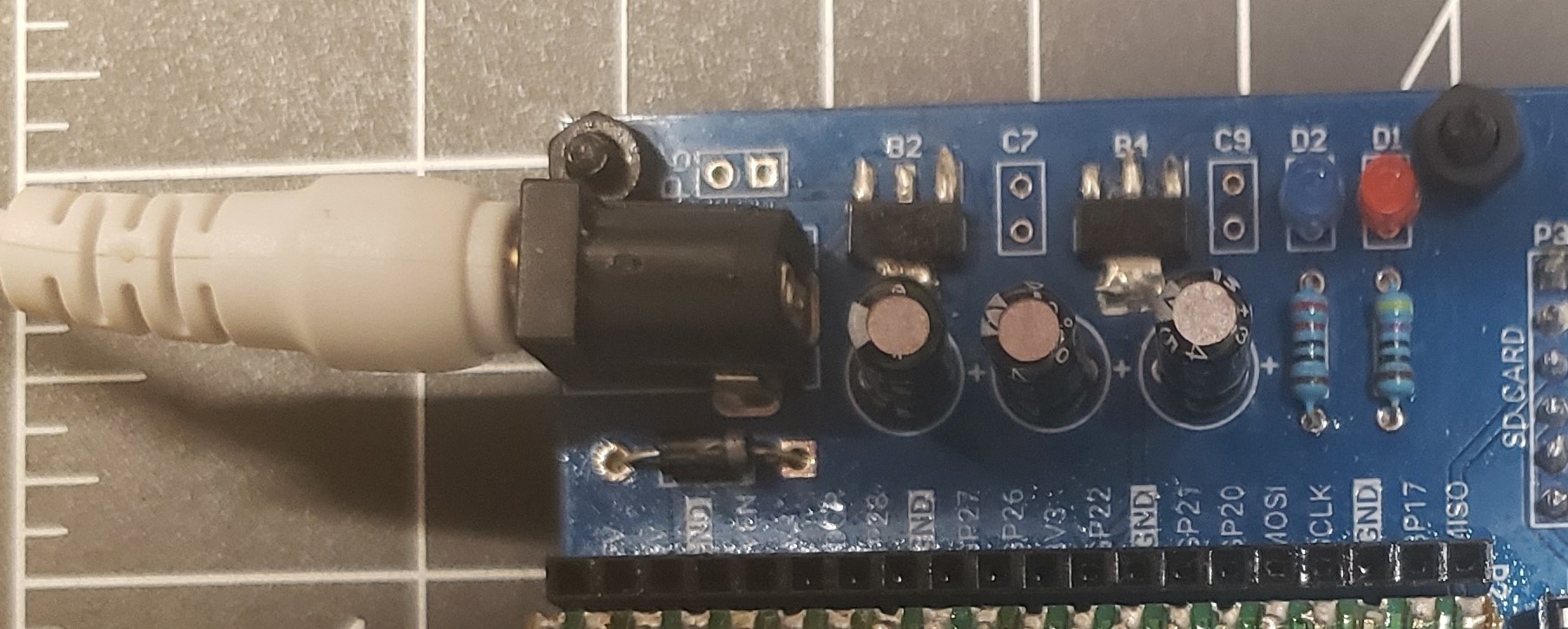
Figure 27: Power regulation system on the PCB
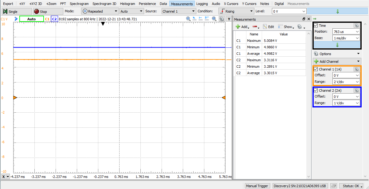
Figure 28: 5V and 3.3V source observed on the oscilloscope.
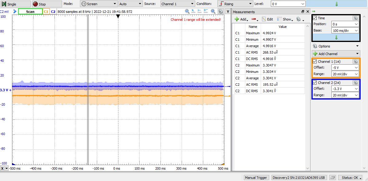
Figure 29: 5V and 3.3V source observed on the oscilloscope, both from a 20mV div.
Appendix
LCD.py
  1# -----------------------------------------
  2#                 NOTES
  3# -----------------------------------------
  4"""
  5Dieter Steinhauser
  65/2023
  7Parallel LCD functions, Configured for 4-bit communication.
  8"""
  9
 10# -----------------------------------------
 11#               IMPORTS
 12# -----------------------------------------
 13
 14from machine import Pin
 15import utime
 16
 17# -----------------------------------------
 18#          CONSTANTS AND VARIABLES
 19# -----------------------------------------
 20
 21# CONSTANTS
 22# ----------------------
 23
 24LCD_CMD = 0
 25LCD_DATA = 1
 26
 27# ----------------------
 28# GPIO Wiring: Legacy Structure
 29# ----------------------
 30
 31# EN = Pin(0, Pin.OUT) # Enable Pin
 32# RS = Pin(1, Pin.OUT) # Register Select
 33
 34# PINS = [2, 3, 4, 5]
 35# Pin numbers for the upper nibble, does the below assignment in configure method.
 36# D4 = Pin(2, Pin.OUT)
 37# D5 = Pin(3, Pin.OUT)
 38# D6 = Pin(4, Pin.OUT)
 39# D7 = Pin(5, Pin.OUT)
 40
 41# list that gets populated with pinout objects for data line.
 42# DATA_BUS = []
 43
 44# -----------------------------------------
 45#                 METHODS
 46# -----------------------------------------
 47
 48# def Configure():
 49#     """Creates the data bus object from the pin list"""
 50
 51#     for index in range(4):
 52#        DATA_BUS.append(Pin(PINS[index], Pin.OUT))
 53
 54# # -----------------------------------------
 55
 56# def lcd_strobe():
 57#     """Flashes the enable line and provides wait period."""
 58
 59#     EN.value(1)
 60#     utime.sleep_ms(1)
 61
 62#     EN.value(0)
 63#     utime.sleep_ms(1)
 64
 65# # -----------------------------------------
 66
 67# def lcd_write(command, mode):
 68#     """Sends data to the LCD module. """
 69
 70#     # determine if writing a command or data
 71#     data = command if mode == 0 else ord(command)
 72
 73#     # need upper nibble for first loop. lower nibble can use data directly.
 74#     upper = data >> 4
 75
 76#     # write the upper nibble
 77#     for index in range(4):
 78#         bit = upper & 1
 79#         DATA_BUS[index].value(bit)
 80#         upper = upper >> 1
 81
 82#     # strobe the LCD, sending the nibble
 83#     RS.value(mode)
 84#     lcd_strobe()
 85
 86#     # write the lower nibble
 87#     for index in range(4):
 88#         bit = data & 1
 89#         DATA_BUS[index].value(bit)
 90#         data = data >> 1
 91
 92#     # Strobe the LCD, sending the nibble
 93#     RS.value(mode)
 94#     lcd_strobe()
 95#     utime.sleep_ms(1)
 96#     RS.value(1)
 97
 98# # -----------------------------------------
 99
100# def lcd_clear():
101#     """Clear the LCD Screen."""
102
103#     lcd_write(0x01, 0)
104#     utime.sleep_ms(5)
105
106# # -----------------------------------------
107
108# def lcd_home():
109#     """Return the Cursor to the starting position."""
110
111#     lcd_write(0x02, 0)
112#     utime.sleep_ms(5)
113
114# # -----------------------------------------
115
116
117# def lcd_cursor_blink():
118#     """Have the cursor start blinking."""
119
120#     lcd_write(0x0D, 0)
121#     utime.sleep_ms(1)
122
123# # -----------------------------------------
124
125# def lcd_cursor_on():
126#     """Have the cursor on, Good for debugging."""
127
128#     lcd_write(0x0E, 0)
129#     utime.sleep_ms(1)
130
131# # -----------------------------------------
132
133# def lcd_cursor_off():
134#     """Turn the cursor off."""
135
136#     lcd_write(0x0C, 0)
137#     utime.sleep_ms(1)
138
139# # -----------------------------------------
140
141# def lcd_puts(string):
142#     """Write a string on to the LCD."""
143
144#     for element in string:
145#        lcd_putch(element)
146
147# # -----------------------------------------
148
149# def lcd_putch(c):
150#     """Write a character on to the LCD."""
151#     lcd_write(c, 1)
152
153# # -----------------------------------------
154
155# def lcd_goto(column, row):
156
157
158#     if row == 0:
159#         address = 0
160
161#     if row == 1:
162#         address = 0x40
163
164#     if row == 2:
165#         address = 0x14
166
167#     if row == 3:
168#         address = 0x54
169
170#     address = address + column
171#     lcd_write(0x80 | address, 0)
172
173# # -----------------------------------------
174
175# def lcd_init():
176
177#     # Configure the pins of the device.
178#     Configure()
179#     utime.sleep_ms(120)
180
181#     # clear values on data bus.
182#     for index in range(4):
183#         DATA_BUS[index].value(0)
184#     utime.sleep_ms(50)
185
186#     # initialization sequence.
187#     DATA_BUS[0].value(1)
188#     DATA_BUS[1].value(1)
189#     lcd_strobe()
190#     utime.sleep_ms(10)
191
192#     lcd_strobe()
193#     utime.sleep_ms(10)
194
195#     lcd_strobe()
196#     utime.sleep_ms(10)
197
198#     DATA_BUS[0].value(0)
199#     lcd_strobe()
200#     utime.sleep_ms(5)
201
202#     lcd_write(0x28, 0)
203#     utime.sleep_ms(1)
204
205#     lcd_write(0x08, 0)
206#     utime.sleep_ms(1)
207
208#     lcd_write(0x01, 0)
209#     utime.sleep_ms(10)
210
211#     lcd_write(0x06, 0)
212#     utime.sleep_ms(5)
213
214#     lcd_write(0x0C, 0)
215#     utime.sleep_ms(10)
216
217
218# -----------------------------------------
219#                 LCD Class:
220# -----------------------------------------
221
222
223class LCD:
224    """The LCD class is meant to abstract the LCD driver further and streamline development."""
225
226    CMD_MODE = 0
227    DATA_MODE = 1
228
229    def __init__(self, enable_pin: int, reg_select_pin: int, data_pins: list) -> None:
230        """Object initialization"""
231
232        self.enable_pin = Pin(enable_pin, Pin.OUT)
233        self.reg_select_pin = Pin(reg_select_pin, Pin.OUT)
234        self._data_pins = data_pins
235        self.data_bus = []
236
237        # Configure the pins of the device.
238        self._configure()
239        utime.sleep_ms(120)
240
241    # -----------------------------------------
242
243    def _configure(self):
244        """Creates the data bus object from the pin list. """
245
246        # Configure the pins of the device.
247        for element in self._data_pins:
248            self.data_bus.append(Pin(element, Pin.OUT))
249
250    # -----------------------------------------
251
252    def init(self):
253        """Initializes the LCD for communication."""
254
255        # clear values on data bus.
256        for index in range(4):
257            self.data_bus[index].value(0)
258        utime.sleep_ms(50)
259
260        # initialization sequence.
261        self.data_bus[0].value(1)
262        self.data_bus[1].value(1)
263        self.strobe()
264        utime.sleep_ms(10)
265
266        self.strobe()
267        utime.sleep_ms(10)
268
269        self.strobe()
270        utime.sleep_ms(10)
271
272        self.data_bus[0].value(0)
273        self.strobe()
274        utime.sleep_ms(5)
275
276        self.write(0x28, 0)
277        utime.sleep_ms(1)
278
279        self.write(0x08, 0)
280        utime.sleep_ms(1)
281
282        self.write(0x01, 0)
283        utime.sleep_ms(10)
284
285        self.write(0x06, 0)
286        utime.sleep_ms(5)
287
288        self.write(0x0C, 0)
289        utime.sleep_ms(10)
290
291    # -----------------------------------------
292
293    def strobe(self):
294        """Flashes the enable line and provides wait period."""
295
296        self.enable_pin.value(1)
297        utime.sleep_ms(1)
298
299        self.enable_pin.value(0)
300        utime.sleep_ms(1)
301
302    # -----------------------------------------
303
304    def write(self, command, mode):
305        """Sends data to the LCD module. """
306
307        # determine if writing a command or data
308        data = command if mode == 0 else ord(command)
309
310        # need upper nibble for first loop. lower nibble can use data directly.
311        upper = data >> 4
312
313        # write the upper nibble
314        for index in range(4):
315            bit = upper & 1
316            self.data_bus[index].value(bit)
317            upper = upper >> 1
318
319        # strobe the LCD, sending the nibble
320        self.reg_select_pin.value(mode)
321        self.strobe()
322
323        # write the lower nibble
324        for index in range(4):
325            bit = data & 1
326            self.data_bus[index].value(bit)
327            data = data >> 1
328
329        # Strobe the LCD, sending the nibble
330        self.reg_select_pin.value(mode)
331        self.strobe()
332        utime.sleep_ms(1)
333        self.reg_select_pin.value(1)
334
335    # -----------------------------------------
336
337    def clear(self):
338        """Clear the LCD Screen."""
339
340        self.write(0x01, 0)
341        utime.sleep_ms(5)
342
343    # -----------------------------------------
344
345    def home(self):
346        """Return the Cursor to the starting position."""
347
348        self.write(0x02, 0)
349        utime.sleep_ms(5)
350
351    # -----------------------------------------
352
353
354    def blink(self):
355        """Have the cursor start blinking."""
356
357        self.write(0x0D, 0)
358        utime.sleep_ms(1)
359
360    # -----------------------------------------
361
362    def cursor_on(self):
363        """Have the cursor on, Good for debugging."""
364
365        self.write(0x0E, 0)
366        utime.sleep_ms(1)
367
368    # -----------------------------------------
369
370    def cursor_off(self):
371        """Turn the cursor off."""
372
373        self.write(0x0C, 0)
374        utime.sleep_ms(1)
375
376    # -----------------------------------------
377
378    def print(self, string):
379        """Write a string on to the LCD."""
380
381        for element in string:
382            self._putch(element)
383
384    # -----------------------------------------
385
386    def _putch(self, c):
387        """Write a character on to the LCD."""
388        self.write(c, 1)
389
390    # -----------------------------------------
391
392    def _puts(self, string):
393        """Write a string on to the LCD."""
394
395        for element in string:
396            self._putch(element)
397
398
399    # -----------------------------------------
400    def go_to(self, column, row):
401
402
403        if row == 0:
404            address = 0
405
406        if row == 1:
407            address = 0x40
408
409        if row == 2:
410            address = 0x14
411
412        if row == 3:
413            address = 0x54
414
415        address = address + column
416        self.write(0x80 | address, 0)
417
418
419# -----------------------------------------
420#              END OF FILE
421# -----------------------------------------
sdcard.py
  1"""
  2MicroPython driver for SD cards using SPI bus.
  3
  4Requires an SPI bus and a CS pin.  Provides readblocks and writeblocks
  5methods so the device can be mounted as a filesystem.
  6
  7Example usage on pyboard:
  8
  9    import pyb, sdcard, os
 10    sd = sdcard.SDCard(pyb.SPI(1), pyb.Pin.board.X5)
 11    pyb.mount(sd, '/sd2')
 12    os.listdir('/')
 13
 14Example usage on ESP8266:
 15
 16    import machine, sdcard, os
 17    sd = sdcard.SDCard(machine.SPI(1), machine.Pin(15))
 18    os.mount(sd, '/sd')
 19    os.listdir('/')
 20
 21"""
 22
 23from micropython import const
 24import time
 25
 26
 27_CMD_TIMEOUT = const(100)
 28
 29_R1_IDLE_STATE = const(1 << 0)
 30# R1_ERASE_RESET = const(1 << 1)
 31_R1_ILLEGAL_COMMAND = const(1 << 2)
 32# R1_COM_CRC_ERROR = const(1 << 3)
 33# R1_ERASE_SEQUENCE_ERROR = const(1 << 4)
 34# R1_ADDRESS_ERROR = const(1 << 5)
 35# R1_PARAMETER_ERROR = const(1 << 6)
 36_TOKEN_CMD25 = const(0xFC)
 37_TOKEN_STOP_TRAN = const(0xFD)
 38_TOKEN_DATA = const(0xFE)
 39
 40
 41class SDCard:
 42    def __init__(self, spi, cs):
 43        self.spi = spi
 44        self.cs = cs
 45
 46        self.cmdbuf = bytearray(6)
 47        self.dummybuf = bytearray(512)
 48        self.tokenbuf = bytearray(1)
 49        for i in range(512):
 50            self.dummybuf[i] = 0xFF
 51        self.dummybuf_memoryview = memoryview(self.dummybuf)
 52
 53        # initialise the card
 54        self.init_card()
 55
 56    def init_spi(self, baudrate):
 57        try:
 58            master = self.spi.MASTER
 59        except AttributeError:
 60            # on ESP8266
 61            self.spi.init(baudrate=baudrate, phase=0, polarity=0)
 62        else:
 63            # on pyboard
 64            self.spi.init(master, baudrate=baudrate, phase=0, polarity=0)
 65
 66    def init_card(self):
 67        # init CS pin
 68        self.cs.init(self.cs.OUT, value=1)
 69
 70        # init SPI bus; use low data rate for initialisation
 71        self.init_spi(100000)
 72
 73        # clock card at least 100 cycles with cs high
 74        for i in range(16):
 75            self.spi.write(b"\xff")
 76
 77        # CMD0: init card; should return _R1_IDLE_STATE (allow 5 attempts)
 78        for _ in range(5):
 79            if self.cmd(0, 0, 0x95) == _R1_IDLE_STATE:
 80                break
 81        else:
 82            raise OSError("no SD card")
 83
 84        # CMD8: determine card version
 85        r = self.cmd(8, 0x01AA, 0x87, 4)
 86        if r == _R1_IDLE_STATE:
 87            self.init_card_v2()
 88        elif r == (_R1_IDLE_STATE | _R1_ILLEGAL_COMMAND):
 89            self.init_card_v1()
 90        else:
 91            raise OSError("couldn't determine SD card version")
 92
 93        # get the number of sectors
 94        # CMD9: response R2 (R1 byte + 16-byte block read)
 95        if self.cmd(9, 0, 0, 0, False) != 0:
 96            raise OSError("no response from SD card")
 97        csd = bytearray(16)
 98        self.readinto(csd)
 99        if csd[0] & 0xC0 == 0x40:  # CSD version 2.0
100            self.sectors = ((csd[8] << 8 | csd[9]) + 1) * 1024
101        elif csd[0] & 0xC0 == 0x00:  # CSD version 1.0 (old, <=2GB)
102            c_size = csd[6] & 0b11 | csd[7] << 2 | (csd[8] & 0b11000000) << 4
103            c_size_mult = ((csd[9] & 0b11) << 1) | csd[10] >> 7
104            self.sectors = (c_size + 1) * (2 ** (c_size_mult + 2))
105        else:
106            raise OSError("SD card CSD format not supported")
107        # print('sectors', self.sectors)
108
109        # CMD16: set block length to 512 bytes
110        if self.cmd(16, 512, 0) != 0:
111            raise OSError("can't set 512 block size")
112
113        # set to high data rate now that it's initialised
114        self.init_spi(1320000)
115
116    def init_card_v1(self):
117        for i in range(_CMD_TIMEOUT):
118            self.cmd(55, 0, 0)
119            if self.cmd(41, 0, 0) == 0:
120                self.cdv = 512
121                # print("[SDCard] v1 card")
122                return
123        raise OSError("timeout waiting for v1 card")
124
125    def init_card_v2(self):
126        for i in range(_CMD_TIMEOUT):
127            time.sleep_ms(50)
128            self.cmd(58, 0, 0, 4)
129            self.cmd(55, 0, 0)
130            if self.cmd(41, 0x40000000, 0) == 0:
131                self.cmd(58, 0, 0, 4)
132                self.cdv = 1
133                # print("[SDCard] v2 card")
134                return
135        raise OSError("timeout waiting for v2 card")
136
137    def cmd(self, cmd, arg, crc, final=0, release=True, skip1=False):
138        self.cs(0)
139
140        # create and send the command
141        buf = self.cmdbuf
142        buf[0] = 0x40 | cmd
143        buf[1] = arg >> 24
144        buf[2] = arg >> 16
145        buf[3] = arg >> 8
146        buf[4] = arg
147        buf[5] = crc
148        self.spi.write(buf)
149
150        if skip1:
151            self.spi.readinto(self.tokenbuf, 0xFF)
152
153        # wait for the response (response[7] == 0)
154        for i in range(_CMD_TIMEOUT):
155            self.spi.readinto(self.tokenbuf, 0xFF)
156            response = self.tokenbuf[0]
157            if not (response & 0x80):
158                # this could be a big-endian integer that we are getting here
159                for j in range(final):
160                    self.spi.write(b"\xff")
161                if release:
162                    self.cs(1)
163                    self.spi.write(b"\xff")
164                return response
165
166        # timeout
167        self.cs(1)
168        self.spi.write(b"\xff")
169        return -1
170
171    def readinto(self, buf):
172        self.cs(0)
173
174        # read until start byte (0xff)
175        for i in range(_CMD_TIMEOUT):
176            self.spi.readinto(self.tokenbuf, 0xFF)
177            if self.tokenbuf[0] == _TOKEN_DATA:
178                break
179        else:
180            self.cs(1)
181            raise OSError("timeout waiting for response")
182
183        # read data
184        mv = self.dummybuf_memoryview
185        if len(buf) != len(mv):
186            mv = mv[: len(buf)]
187        self.spi.write_readinto(mv, buf)
188
189        # read checksum
190        self.spi.write(b"\xff")
191        self.spi.write(b"\xff")
192
193        self.cs(1)
194        self.spi.write(b"\xff")
195
196    def write(self, token, buf):
197        self.cs(0)
198
199        # send: start of block, data, checksum
200        self.spi.read(1, token)
201        self.spi.write(buf)
202        self.spi.write(b"\xff")
203        self.spi.write(b"\xff")
204
205        # check the response
206        if (self.spi.read(1, 0xFF)[0] & 0x1F) != 0x05:
207            self.cs(1)
208            self.spi.write(b"\xff")
209            return
210
211        # wait for write to finish
212        while self.spi.read(1, 0xFF)[0] == 0:
213            pass
214
215        self.cs(1)
216        self.spi.write(b"\xff")
217
218    def write_token(self, token):
219        self.cs(0)
220        self.spi.read(1, token)
221        self.spi.write(b"\xff")
222        # wait for write to finish
223        while self.spi.read(1, 0xFF)[0] == 0x00:
224            pass
225
226        self.cs(1)
227        self.spi.write(b"\xff")
228
229    def readblocks(self, block_num, buf):
230        nblocks = len(buf) // 512
231        assert nblocks and not len(buf) % 512, "Buffer length is invalid"
232        if nblocks == 1:
233            # CMD17: set read address for single block
234            if self.cmd(17, block_num * self.cdv, 0, release=False) != 0:
235                # release the card
236                self.cs(1)
237                raise OSError(5)  # EIO
238            # receive the data and release card
239            self.readinto(buf)
240        else:
241            # CMD18: set read address for multiple blocks
242            if self.cmd(18, block_num * self.cdv, 0, release=False) != 0:
243                # release the card
244                self.cs(1)
245                raise OSError(5)  # EIO
246            offset = 0
247            mv = memoryview(buf)
248            while nblocks:
249                # receive the data and release card
250                self.readinto(mv[offset : offset + 512])
251                offset += 512
252                nblocks -= 1
253            if self.cmd(12, 0, 0xFF, skip1=True):
254                raise OSError(5)  # EIO
255
256    def writeblocks(self, block_num, buf):
257        nblocks, err = divmod(len(buf), 512)
258        assert nblocks and not err, "Buffer length is invalid"
259        if nblocks == 1:
260            # CMD24: set write address for single block
261            if self.cmd(24, block_num * self.cdv, 0) != 0:
262                raise OSError(5)  # EIO
263
264            # send the data
265            self.write(_TOKEN_DATA, buf)
266        else:
267            # CMD25: set write address for first block
268            if self.cmd(25, block_num * self.cdv, 0) != 0:
269                raise OSError(5)  # EIO
270            # send the data
271            offset = 0
272            mv = memoryview(buf)
273            while nblocks:
274                self.write(_TOKEN_CMD25, mv[offset : offset + 512])
275                offset += 512
276                nblocks -= 1
277            self.write_token(_TOKEN_STOP_TRAN)
278
279    def ioctl(self, op, arg):
280        if op == 4:  # get number of blocks
281            return self.sectors
test.py
  1# -----------------------------------------
  2#                 NOTES
  3# -----------------------------------------
  4"""
  5Dieter Steinhauser
  612/2022
  7PicoPAD Test Script
  8
  9"""
 10
 11# -----------------------------------------
 12#               IMPORTS
 13# -----------------------------------------
 14
 15from LCD import LCD
 16# import _thread
 17from utime import sleep, sleep_ms, sleep_us, ticks_ms
 18from machine import Pin, Timer, ADC, freq
 19# import gc
 20
 21# -----------------------------------------
 22#         CONSTANTS/VARIABLES
 23# -----------------------------------------
 24
 25# ------------------
 26REFRESH_RATE = 10 # Frequency in Hz
 27REFRESH_PERIOD = int((1 / REFRESH_RATE) * 1000) # delay in milliseconds
 28
 29# ------------------
 30UPY_BIT_RES = 16
 31ADC_REF = 3.3
 32VOLT_PER_BIT = ADC_REF / (2**UPY_BIT_RES) # ADC recieves in 2 byte packets and micropython automagically fixes it.
 33
 34# ------------------
 35DAC_REF = 5.0
 36DC_OFFSET = 0
 37DC_OFFSET_RES = int((DC_OFFSET / DAC_REF) * (2**UPY_BIT_RES))
 38
 39# ------------------
 40FREQ_MAX = 160
 41FREQ_MIN = 10
 42AMP_MAX = DAC_REF
 43AMP_MIN = 0
 44
 45MAX_DIST_US0 = 50
 46MAX_DIST_US1 = 20
 47
 48
 49# -------------------------------------------------------------
 50#           INITIALIZATION
 51# -------------------------------------------------------------
 52
 53# -----------------------------------------
 54#           SYSTEM CLOCK
 55# -----------------------------------------
 56
 57DEFAULT_SYS_CLK = 125_000_000
 58STABLE_OVERCLOCK = 270_000_000
 59
 60# Pico can go up to 270MHz before needing to flash to the eeprom directly.
 61system_clock = DEFAULT_SYS_CLK
 62
 63# if the system clock is not the default, apply the clock speed.
 64if system_clock !=  DEFAULT_SYS_CLK:
 65    freq(system_clock)
 66
 67# print(f'Clock: {freq()/1e6}MHz')
 68
 69# -----------------------------------------
 70#               PINOUT
 71# -----------------------------------------
 72
 73# LCD Pins handled in LCD.py
 74# ----------------------------
 75# EN = Pin(0, Pin.OUT)
 76# RS = Pin(1, Pin.OUT)
 77# D7 = Pin(2, Pin.OUT)
 78# D6 = Pin(3, Pin.OUT)
 79# D5 = Pin(4, Pin.OUT)
 80# D4 = Pin(5, Pin.OUT)
 81
 82# Ultrasonic sensor pins handled in sensors.py
 83# ----------------------------
 84# us0_trig = Pin(6, Pin.OUT)
 85# us0_echo = Pin(7, Pin.IN)
 86# us1_trig = Pin(8, Pin.OUT)
 87# us1_echo = Pin(9, Pin.IN)
 88
 89# Switches
 90# ----------------------------
 91# sw0 = Pin(10, Pin.IN, Pin.PULL_DOWN)
 92# sw1 = Pin(11, Pin.IN, Pin.PULL_DOWN)
 93# sw2 = Pin(12, Pin.IN, Pin.PULL_DOWN)
 94# sw3 = Pin(13, Pin.IN, Pin.PULL_DOWN)
 95# switch_pins = [sw0, sw1, sw2, sw3]
 96
 97# LEDs
 98# ----------------------------
 99# led0 = Pin(14, Pin.OUT)
100# led1 = Pin(15, Pin.OUT)
101led_onboard = Pin(25, Pin.OUT)
102# led_pins = [led0, led1, led_onboard]
103
104# SPI handled by the Hardware in spi_config.py
105# ----------------------------
106# miso = Pin(16, Pin.IN)
107# cs = Pin(17, Pin.OUT, value=1)
108# mosi = Pin(18, Pin.OUT)
109# sck = Pin(19, Pin.OUT)
110
111# Buttons
112# ----------------------------
113# button0 = Pin(20, Pin.IN)
114# button1 = Pin(21, Pin.IN)
115# button2 = Pin(22, Pin.IN)
116# button3 = Pin(28, Pin.IN)
117# button_pins = [button0, button1, button2, button3]
118
119# ADC
120# ----------------------------
121# adc0 = ADC(26) # Connect to GP26, which is channel 0
122# adc1 = ADC(27) # Connect to GP27, which is channel 1
123
124# -----------------------------------------
125#           LCD
126# -----------------------------------------
127lcd = LCD(enable_pin=0,
128         reg_select_pin=1,
129         data_pins=[2, 3, 4, 5]
130         )
131
132lcd.init()
133lcd.clear()
134# lcd.cursor_on()
135# lcd.blink()
136# -----------------------------------------
137#           ADC
138# -----------------------------------------
139adc0 = ADC(26) # Connect to GP26, which is channel 0
140adc1 = ADC(27) # Connect to GP27, which is channel 1
141# adc2 = machine.ADC(28) # Connect to GP28, which is channel 2
142# adc_reading = adc0.read_u16() * VOLT_PER_BIT # read and report the ADC reading
143
144# -----------------------------------------
145#           SD CARD VIA SPI
146# -----------------------------------------
147#
148# import sdcard
149# import os
150# import uos
151#
152# # Assign chip select (CS) pin (and start it high)
153# cs = Pin(20, machine.Pin.OUT)
154#
155# # Intialize SPI peripheral (start with 1 MHz)
156# spi = machine.SPI(0,
157#                   baudrate=1000000,
158#                   polarity=0,
159#                   phase=0,
160#                   bits=8,
161#                   firstbit=machine.SPI.MSB,
162#                   sck=Pin(18),
163#                   mosi=Pin(19),
164#                   miso=Pin(16))
165#
166# # Initialize SD card
167# sd = sdcard.SDCard(spi, cs)
168#
169# vfs = uos.VfsFat(sd)
170# uos.mount(vfs, "/sd")
171#
172# # Create a file and write something to it
173# file = open("/sd/test01.txt", "w")
174#
175# with open("/sd/test01.txt", "w") as file:
176#     file.write("Hello, SD World!\r\n")
177#     file.write("This is a test\r\n")
178#
179# # Open the file we just created and read from it
180# with open("/sd/test01.txt", "r") as file:
181#     data = file.read()
182#     print(data)
183
184# -----------------------------------------
185#           PROCESS 1: IO
186# -----------------------------------------
187
188while True:
189
190    splash = True
191    # Display the splash screen on startup.
192    if splash is True:
193        led_onboard(1)
194        lcd.print(f'PicoPAD Test  ')
195        lcd.go_to(0,1)
196        lcd.print(f'Dieter S.        ')
197        sleep(2)
198        lcd.home()
199        lcd.clear()
200        lcd.print(f'System Clock')
201        lcd.go_to(0,1)
202        lcd.print(f'{freq()/1e6}MHz')
203        sleep(2)
204        lcd.home()
205        lcd.clear()
206        led_onboard.toggle()
207
208    while True:
209
210        # read ADC
211        # -----------------------------------------
212        adc0_reading = (adc0.read_u16() * VOLT_PER_BIT)
213        adc1_reading = (adc1.read_u16() * VOLT_PER_BIT)
214        lcd.home()
215        lcd.print(f'ADC0: {round(adc0_reading,3)}       ')
216        lcd.go_to(0,1)
217        lcd.print(f'ADC1: {round(adc1_reading,3)}       ')
218
219        # toggle onboard LED for System speed status and refresh delay
220        # -----------------------------------------
221        led_onboard.toggle()
222        sleep_ms(REFRESH_PERIOD)
223        # gc.collect()
224
225
226
227
References
- 2
“What is a bypass capacitor? tutorial: Applications,” Electronics Hub, 14-Sep-2021. [Online]. Available: https://www.electronicshub.org/bypass-capacitor-tutorial/. [Accessed: 27-Aug-2022].
- 10
“Ltc1661 – micropower dual 10-bit DAC in MSOP - Analog Devices.” [Online]. Available: https://www.analog.com/media/en/technical-documentation/data-sheets/1661fb.pdf. [Accessed: 17-Oct-2022].
- 13(1,2,3,4)
“Raspberry Pico Datasheet,” raspberrypi.com. [Online]. Available: https://datasheets.raspberrypi.com/pico/pico-datasheet.pdf. [Accessed: 15-Nov-2022].
- 14(1,2)
“Raspberry Pico python SDK,” raspberrypi.com. [Online]. Available: https://datasheets.raspberrypi.com/pico/raspberry-pi-pico-python-sdk.pdf. [Accessed: 15- Nov-2022].
- 15
“RP2040 Datasheet,” raspberrypi.com. [Online]. Available: https://datasheets.raspberrypi.com/rp2040/rp2040-datasheet.pdf. [Accessed: 14-Nov-2022].
- 16
“Serial peripheral interface,” Wikipedia, 27-Sep-2022. [Online]. Available: https://en.wikipedia.org/wiki/Serial_Peripheral_Interface. [Accessed: 19-Oct-2022].
- 17
“Sitronix ST7066U - Crystalfontz,” crystalfontz. [Online]. Available: https://www.crystalfontz.com/controllers/Sitronix/ST7066U/438. [Accessed: 03-Oct2022].
- 18
“What is a Bypass Capacitor?,” What is a bypass capacitor? [Online]. Available: http://www.learningaboutelectronics.com/Articles/What-is-a-bypass-capacitor.html. [Accessed: 27-Aug-2022].