GatorCade: RetroPi Arcade Cabinet
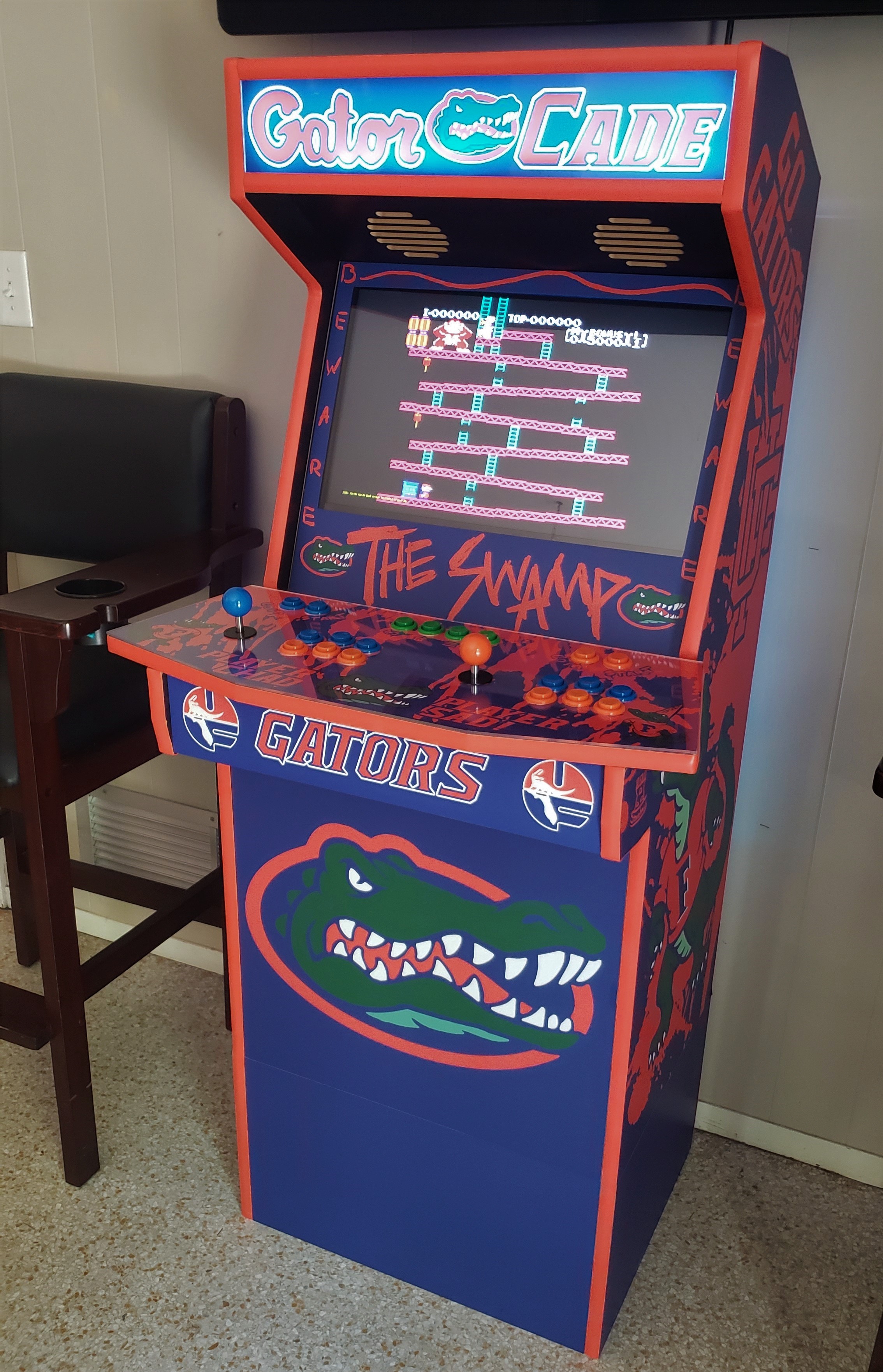
The finished cabinet, playing the NES version of Donkey Kong.
Summary
I built an arcade cabinet using a Raspberry Pi 3b running RetroPie on Emulation Station. The core system can emulate retro games well with any USB input and HDMI output. However, the Raspberry Pi’s hardware is best used for games using 2D graphics. In other words, the hardware works best with games of the NES, SNES, and Arcade era of video games. This era of games is easily mapped to gamepad controls as most titles require no more than 4 axis movement and a few buttons. Overall, the project required two months from start to finish, as sourcing parts and the planning stage is key for a polished result.
- The purposes of this project:
Learn about the Linux environment
Apply basic circuit concepts
Reinforce soldering techniques
Have the end-user to have a video game emulator within an arcade cabinet.
Tools
Soldering Iron, solder, and wick
Box cutter
Cordless drill
Phillips’s screwdriver
Wire strippers
Rubber mallet
Computer
Materials
Surge Protector
Arcade 2 player controller microcontroller (Xin Mo) & Arcade wiring kit
128gb SD card (user choice for size)
Preparation
The first step of this process was to find a source for the cabinet of the machine. I was unable to undertake a woodworking project of this magnitude at the time, so I found a company called Game Room Solutions who fabricates MDF cabinets for this specific purpose. This company also offers vinylwrapping of their cabinets and allows customers to design their own wraps. For this, I reached out to my brother to assist in the graphic design. Together we designed a custom University of Florida Gators skin that came out beautifully. I then took the vector images and designed the cabinet in Fusion360 to better visualize the custom wrap. Upon sending the designs back to the company, I waited 2-3 weeks before receiving the product.
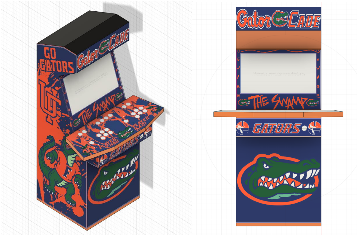
CAD models with imported imagery used for the arcade cabinet.
After securing the cabinet, sourcing the internals was the next major step. The company mentioned above offers everything needed at a premium. I sought other avenues to get the internals for better price and customization of the Cabinet. This also let me acquire the Raspberry Pi faster and work on setting up the emulator.
Assembly
Emulator Setup
Flashing a copy of RetroPie to a MicroSD card. This can be done in a variety of software, but I would suggest win32 disk imager and the official Raspberry Pi imager for this task. Distributions of Linux specifically for Pi’s are easily found when going to Raspberry Pi’s website, or with a quick google search.
The next step was adding games to the library, which I cannot tell you in detail. This step was essentially copying files to specific game directories. There are many resources for this if you look for them. After inserting the microSD into the Pi and doing some configuring with the mouse and keyboard, I was set to start working on the full assembly.
Cabinet Assembly
Once the cabinet arrived, I started assembling the cam-lock cabinet, much like IKEA furniture. This took a few days on-and-off to assemble, as there were no specific instructions that came with the cabinet. The largest issues faced were in mounting the monitor within the cabinet. This varies depending on the type of monitor used, as the HDMI port location changes between models. The important part is to acquire a slim monitor with a VESA mount.
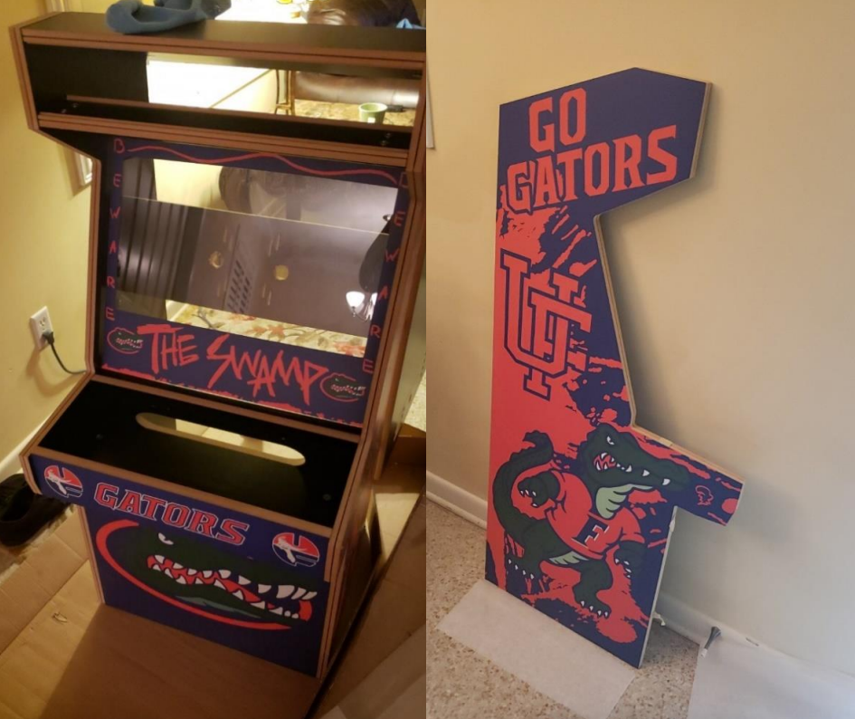
Assembly of the Cabinet
After careful measurement and a few well-placed holes, the monitor was mounted, cables were run, and gaps in the screen were covered with tape to reduce light shining between the monitor and the front panel. The next step was to add the T-molding to the entirety of the machine, which required a precise cut to get the trim looking seamless. Precision of this step creates a very professional touch.
Gamepad Wiring
When the base assembly was finished, insertion of buttons and joysticks were needed to complete the exterior. Wiring of the joysticks is relative to the microcontroller, but a daisy chained Vcc line is sent to every button that completes the circuit to the microcontroller GPIO (Figure 6). The Joystick is a bit more complex with five wires for power and data transmission.
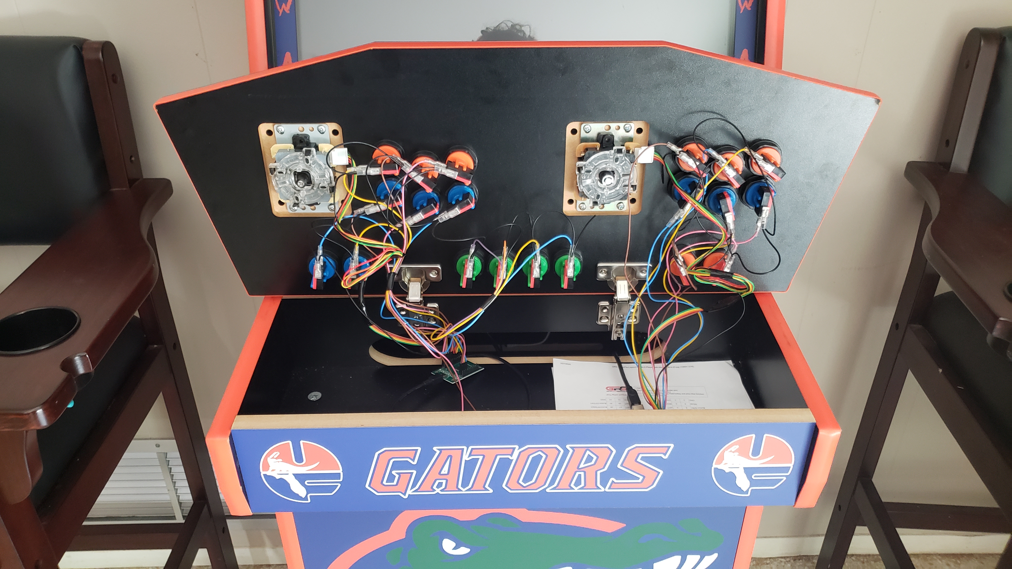
Wiring to the Joysticks and buttons to the microcontroller.
The microcontrollers used were Xin-Mo gamepad controllers, allowing simple controller inputs to be received and sent to the Pi via serial communication. I used the one I found based simply by finding a gamepad bundle that also included the buttons, wiring, and joysticks. Wiring was a tedious process but incredibly rewarding. The microcontroller was then connected via mini-USB to USB on the Raspberry Pi.
Peripherals and Power
Next was to finish off the internals. Sound, lighting, and power needed in the cabinet before everything could be connected to the raspberry Pi. Sound of the system would be output from a 3.5mm jack to a 12V 150W stereo amplifier for two speakers mounted on the system. LED light strips were added to the arcade marquee as well as the back of the machine to add front and back lighting to the system.
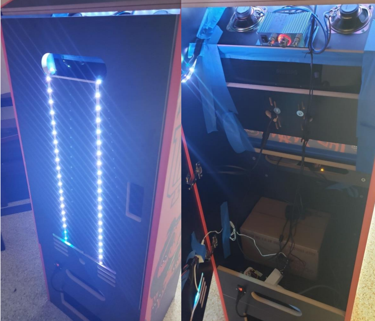
Lighting, sound, power, and other internals to the Arcade Cabinet system. Painter’s tape is applied liberally to block marquee light from bleeding through the front panel.
A power strip with surge protection was added to the machine to power the monitor, lights, amplifier, and Microprocessor. To control system power, a switch socket was added the back of the cabinet and leads more effectively from the end of the power strip were soldered to the socket. A 120V AC three prong power cord was then used to power the whole machine with a simple cutoff switch behind the cabinet.